Varun Brahmadin's Documentation
<h1> chapter 10. Interface & Application Programming </h1>
Objectives
Wk 1
[x] Setup Dev Environment for ESP32 S2
[x] Setup NodeJS Dev Environment on your PC
[ ] Explain the HackOmation quadrant in relation to your final project.
[x] Build UI mockups for your FInal Project and HTML Layout
Wk 2
[x] Build HTML5 Chat app
Draw mockup / layout
frame and add id’s to <div>’s
Style the page and
wire up the JS code and understand
Wk 3
[ ] Build Chat app back-end NodeJS
Build NodeJS server side to:
host your ChatApp (Express static HTML)
Build / test API endpoints (for: users & messages)
Wk 4
[ ] Setup MongoDB datastore & connect via NodeJS
Setup MongoDB datastore + mongoose ODM (Object-Document-Manager)
Store and recall message data using an API (ex. request top 100 msg)
Wire up MongoDB to API endpoints
Update app-flow to use back-end for Users and “old” messages
Wk 5
[ ] Create data-bound widgets to display sensor data
On ESP32 add MQTT client + ArduinoJSON
Send Sensor data to MQTT server (as a JSON object)
Create a DataCard, a Gauge and a time Chart widget on Dashboard (use chat app)
Strategy on DataBinding and Widget updating (Last updated)
User Login/Pw (state persistence)
[x] Add Screenshots and description of the process of creating your board.
[x] Describe the design & programming steps
[x] Screenshots or video of your Prototype/app working
[x] Describe any errors or problems with the process and how you fixed them.
[x] Include all the files you created for download.
10.1 Build HTML5 Chat app
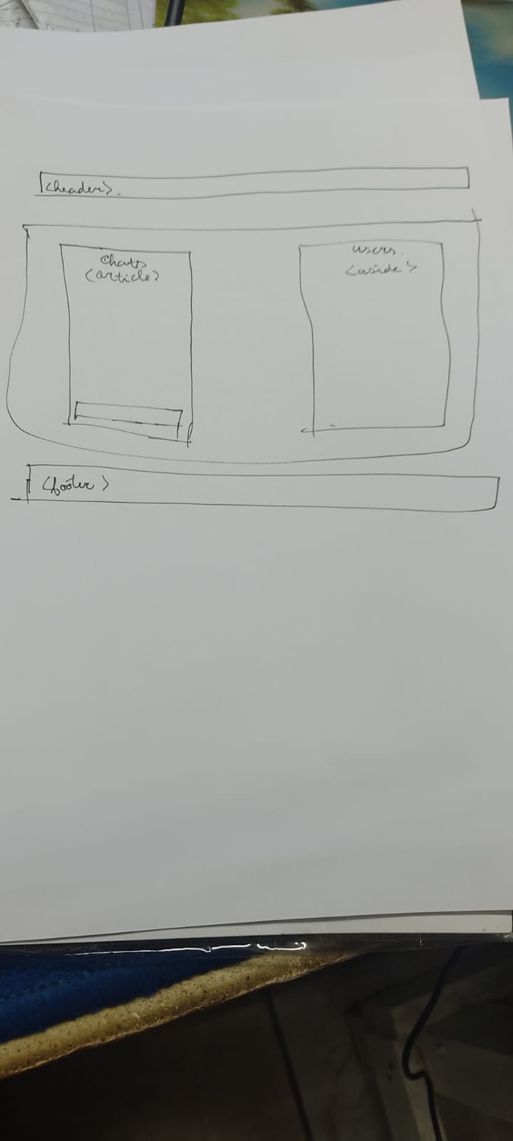
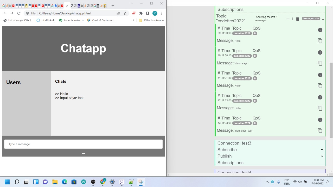
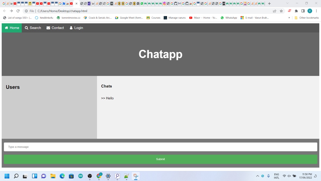
So our objective was to build a chat app with a mqtt server. We first started by installing mqtt lens so we can connect to a public server. After that we made our mockups(pic 1) and put the drawings into code. After that we connected to the mqtt server with javascript, to make sure we had a connection. After that it was just adding functions and building a front end for it. After I connected to the mqtt server(pic2), I could send and receive messages(pic3). I worked on the front end and styled it with css(pic 4)
Here we have my mockup
After that we build our app with just the tags and the basic setup and connected it with a basic script.
After we had connected to the mqtt server, It was just a matter of styling and building extra features,
In the first picture, i have already connect to the mqtt server, but i couldnt send messages. Was a coding error, but it got fixed pretty soon
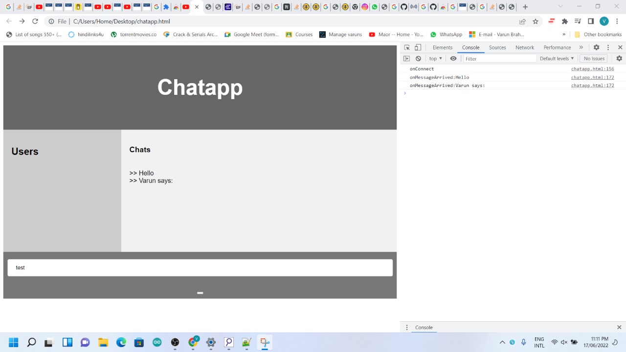
In the second picture, I can now write from the chat app and also read, So i had the basics covered
In the last pic i just styled it with css
Problems
- mqtt server
- Lessons learned
- I got my web dev skills back, i forgot most of the tags tbh, but yeah refreshed it, Owh i learned javascript i never really went into that, and i also got working with mqtt servers and how those work
Files & Downloads
Code:
<!DOCTYPE html>
<html lang="en">
<head>


<script src="https://cdnjs.cloudflare.com/ajax/libs/paho-mqtt/1.0.1/mqttws31.js" type="text/javascript"></script>
<script src="https://cdnjs.cloudflare.com/ajax/libs/mqtt/4.3.7/mqtt.min.js" type="text/javascript"></script>
<link rel="stylesheet" href="https://cdnjs.cloudflare.com/ajax/libs/font-awesome/4.7.0/css/font-awesome.min.css">


<link rel="stylesheet" href="https://cdn.jsdelivr.net/npm/bootstrap@4.0.0/dist/css/bootstrap.min.css" integrity="sha384-Gn5384xqQ1aoWXA+058RXPxPg6fy4IWvTNh0E263XmFcJlSAwiGgFAW/dAiS6JXm" crossorigin="anonymous">


<title>Chatt app</title>
<!--<link rel="icon" type="image/x-icon" href="logo.png"> -->
<meta charset="utf-8">
<meta name="viewport" content="width=device-width, initial-scale=1">


<style>

* {
  box-sizing: border-box;
}

body {
  font-family: Arial, Helvetica, sans-serif;
}

/* Style the header */
header {
  background-color: #d3d3d3;
  padding: 30px;
  text-align: center;
  font-size: 35px;
  color: white;
}

/* Create two columns/boxes that floats next to each other */
aside {
  float: left;
  width: 15%;
  height: 326px; /* only for demonstration, should be removed */
  background: #ccc;
  padding: 20px;
}

/* Style the list inside the menu */
nav ul {
  list-style-type: none;
  padding: 0;
}

article {
  float: left;
  padding: 20px;
  width: 85%;
  background-color:#524f4f;
  overflow:auto;

  height: 326px; /* only for demonstration, should be removed */
}

/* Clear floats after the columns */
section::after {
  content: "";
  display: table;
  clear: both;

}

/* Style the footer */
footer {
  background-color: #777;
  padding: 10px;
  text-align: center;
  color: white;
}

/* Responsive layout - makes the two columns/boxes stack on top of each other instead of next to each other, on small screens */
@media (max-width: 600px) {
  nav, article {
    width: 100%;
    height: auto;
  }
}


#cbox{

 align: bottom;

}

.cinput, select {
  width: 100%;
  padding: 12px 20px;
  margin: 8px 0;
  display: inline-block;
  border: 1px solid #ccc;
  border-radius: 4px;
  box-sizing: border-box;
}


#submit {
  width: 100%;
  background-color: #4CAF50;
  color: white;
  padding: 14px 20px;
  margin: 8px 0;
  border: none;
  border-radius: 4px;
  cursor: pointer;
}

#submit:hover {
  background-color: #45a049;
}


.navbar {
  width: 100%;
  background-color: #555;
  overflow: auto;
}

.navbar a {
  float: left;
  padding: 12px;
  color: white;
  text-decoration: none;
  font-size: 17px;
}

.navbar a:hover {
  background-color: #000;
}

.active {
  background-color: #04AA6D;
}

@media screen and (max-width: 500px) {
  .navbar a {
    float: none;
    display: block;
  }
}


h5{

background-color: black;
color: white;
padding: 6px 7px 8px 9px;
box-sizing: border-box;

}

.list-group list-group-flush{
background-color:black;


}


.pp {
  border: none;
  color: black;
  #padding: 8px 16px;
  text-align: center;
  text-decoration: none;
  display: inline-block;
  font-size: 14px;
  margin: 0px 4px;
  cursor: pointer;
  float: left;
}

.con {
  border: none;
  color: black;
  #padding: 8px 16px;
  text-align: center;
  text-decoration: none;
  display: inline-block;
  font-size: 14px;
  margin: 0px 4px;
  cursor: pointer;
  float: left;
}


</style>

</head>
<body>

<div class="navbar">
  <a class="active" href="#"><i class="fa fa-fw fa-home"></i> Home</a>
  <a href="#"><i class="fa fa-fw fa-search" ></i> Search</a>
  <a href="#"><i class="fa fa-fw fa-envelope"></i> Contact</a>
  <a href="#"><i class="fa fa-fw fa-user"></i> Login</a>
  <input id ="username" class="usernam" type="text" placeholder="Type a message"></input>
</div>


<header>
  <h3>Chatapp</h3>
  <button  class="pp" onclick="connect(sendPing())">Ping </button>
  <button class="pp" onclick="sendPong()">Pong </button>
  <button class="con" onclick="connect()">connect </button>
</header>

<section>
 <aside>
 <h1>Users</h1>
 <div id="userlist"></div>

  </aside>

   <article id="chatlog">
    <h1>Chats</h1>
  </article>

</section>


<footer >
  <input id ="chatInput" class="cinput" type="text" placeholder="Type a message" onkeydown="sendMsg(this)"></input><br>

<button id="submit"  onclick="sendMessageButton(getElementById('chatInput').value); getElementById('chatInput').value='';">Submit </button>

</footer>
<script>


	// Chat app MQTT settings
	var mqttServer = "ws://broker.hivemq.com:8000/mqtt";
	var mqttTopic= "codettes2022";
	var userName = document.getElementById("username").value ||"Varun";
	const clientId = 'cb22_' + Math.random().toString(16).substr(2, 8)
	var userList = [];

//var client ;

	// Chat app MQTT settings
	//var mqttServer = "ws://broker.hivemq.com:8000/mqtt";
	//var mqttTopic= "codettes2022";
	//var userName = document.getElementById("username").value ||"Varun";
	//const clientId = 'cb22_' + Math.random().toString(16).substr(2, 8)
	//var userList = [];

	const opts = {
	  keepalive: 30,
	  clientId: clientId,
	  protocolId: 'MQTT',
	  protocolVersion: 4,
	  clean: true,
	  reconnectPeriod: 1000,
	  connectTimeout: 30 * 1000,
	  will: {
	    topic: 'WillMsg',
	    payload: 'Connection Closed abnormally..!',
	    qos: 0,
	    retain: false
	  },
	  rejectUnauthorized: false
	}

	console.log('connecting mqtt client')
	var client = mqtt.connect(mqttServer, opts);


	client.on('error', function (err) {
	  console.log(err)
	  client.end()
	})

	client.on('connect', function () {
	  // Once a connection has been made, make a subscription and send a message.
	  console.log('client connected:' + clientId)
	  client.subscribe(mqttTopic, { qos: 0 })
	  client.publish(mqttTopic, userName + " signed on!", { qos: 0, retain: false })
	  sendPong();
	})


	client.on('message', function (topic, message, packet) {
	  msg = message.toString(); // library delivers  buffer so convert to strig first
	  console.log("onMessageArrived: "+ msg);
	  // if it has JSON payload do NOT add to chat
	  try{
	  	msgObj = JSON.parse(message.toString()); // t is JSON so handle it how u want
	  	// if message has Pin of Pong in it send it to the PingPongHandler
	  	if (Object.keys(msgObj)[0] == "ping"){sendPong();};
	  	if (Object.keys(msgObj)[0] == "pong"){handlePong(msgObj.pong);}; // pong value is an object!!
	  	// other handlers for control messages below

	  }catch {
	  	document.getElementById("chatlog").innerHTML += "<br> >> " + msg;
	  }
	})

	client.on('close', function () {
	  console.log(clientId + ' disconnected')
	})


	function sendMessageButton(msgtext){
	  	if (msgtext!=''){
			var name={varun};
			client.publish(mqttTopic, userName + " says: " + msgtext+ JSON.stringify(name));
		}
	}

	// OR listen to the Enter event on n input box
	function sendMsg(ele) {
	    if(event.key === 'Enter') {
			client.publish(mqttTopic, userName + " says: " + ele.value);
	        //alert(ele.value);
	        ele.value = ""; // reset the input after entering
	    }
	}

	// --- To manage userlist implement a PING and PONG system ---
	// Ping will request an "alive sign" from all or any user
	// Pong function will respond to ping
	// handlePong pongs in the UI
	// Ping will be scheduled to run regularly as a KeepAlive signal

	function sendPing(usr='*'){
		// ping sends out a message to all (*) or any specific user to respond if ur there
		var pingObj={ping:usr};
		client.publish(mqttTopic, JSON.stringify(pingObj));
	}

	function sendPong(){
		// sends clientID and UserName in a JSON object (and whatever u need more)
		var pongObj={pong :{userName : userName, clientId:clientId}};
		client.publish(mqttTopic, JSON.stringify(pongObj));
		console.log(JSON.stringify(pongObj));
	}

	// function that manages the UserList and other UI stuff related to PingPong
	function handlePong(pongObj){
		// Update Userlist with Pongs
		const index = userList.findIndex(object => {
		  return object.userName === pongObj.userName;
		});

		//console.log("index:" + index);
		if(index>=0){
			console.log("User exists");
			userList[index] = pongObj;
		} else{
	    	console.log("New User " + pongObj.userName);
	    	userList.push(pongObj);
		}
		//console.log(userList);
		redrawUserList();
	}

	function redrawUserList(){
		// Generate the userlist HTML
		var ulist="<ul>";
		userList.forEach(function (item) {
		    //var x = arrayItem.prop1 + 2;
		    ulist+= "<li>"+ item.userName + " <a href='#" + mqttTopic + "/" + item.clientId +"'><i class='fa fa-fw fa-phone'></i></a></li>"
		});
		ulist+="</ul>";
		//console.log(ulist);
		document.getElementById("userlist").innerHTML= "<br> >> " + ulist;
	}
	// to keep connection alive
	//setInterval(sendPong, 10000); // keeps ponging every 10 secs

</script>

</body>
</html>
Chapter 7: 3D Printing
3D Printing is putting layers of a material(filament) on top of each other. The material we use is pla or abs.So we also need to configure our cura for the specific 3d printer. We are gonna use the Anycubic Predator
Filament types we can use: PLA, ABS
PLA and ABS are both thermoplastics. PLA is stronger and stiffer than ABS, but poor heat-resistance properties means PLA is mostly a hobbyist material. ABS is weaker and less rigid, but also tougher and lighter, making it a better plastic for prototyping applications.
7.1 Cura
First we need to install Cura version 5.0.0:
And just click through it
Add the Printer
Go to Settings - Printer - Add Printer
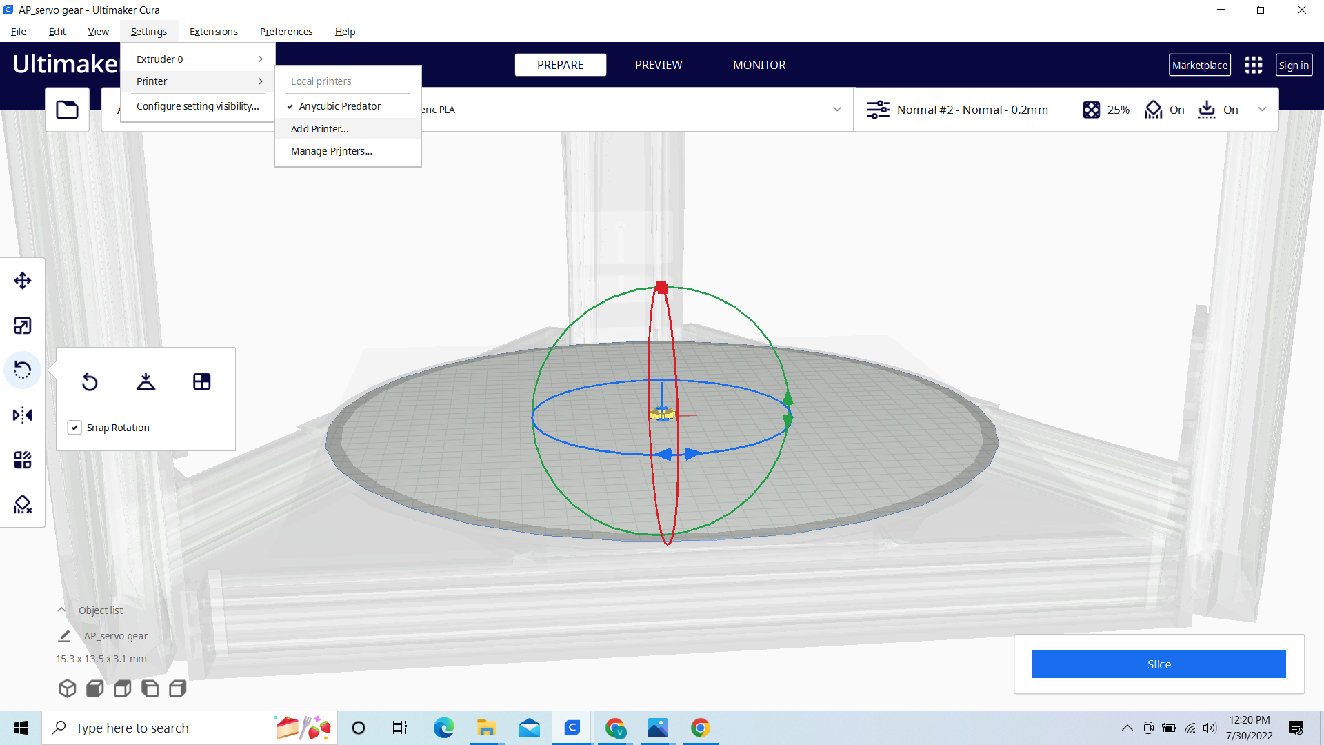
Add a non-networked printer- Anycubic - Anycubic Predator
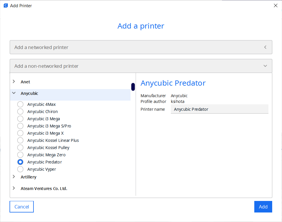
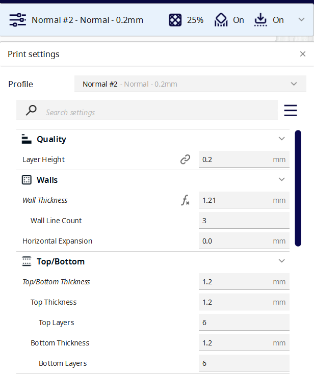
Put Parameters
These parameters are for PLA on the Anycubic predator
Settings changed:
Walls: Wall thickness: 1.21
Top/Bottom: Top/Bottom Thickness 1.2
Material:
Printing Temperature: 195
Build Plate Temperature: 60
Travel:
Enable Retraction: check
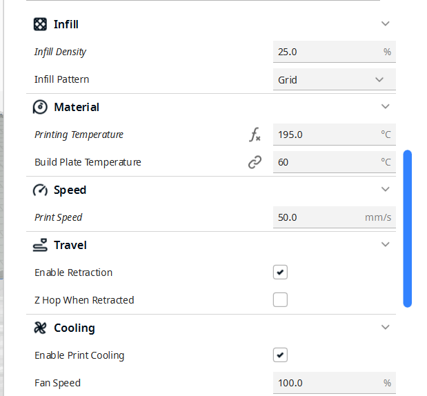
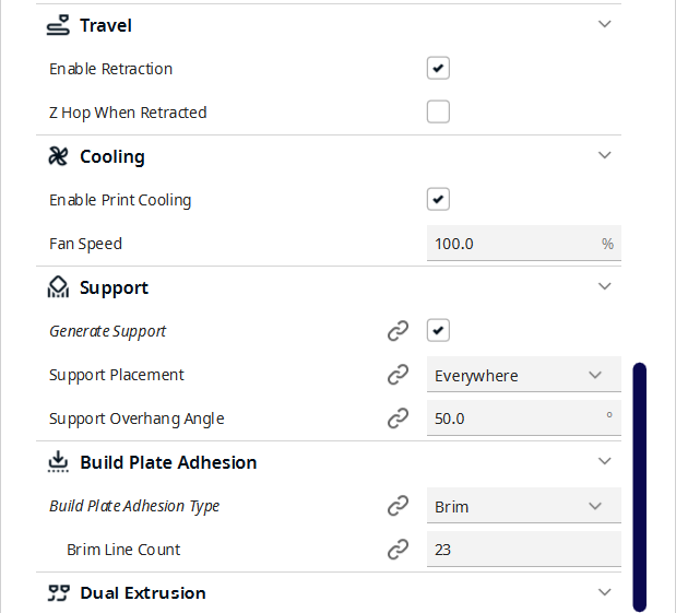
These are the parameters. Now we need to adjust them.
7.2 STL
I open tinkercad then 3d design and i wrote my name
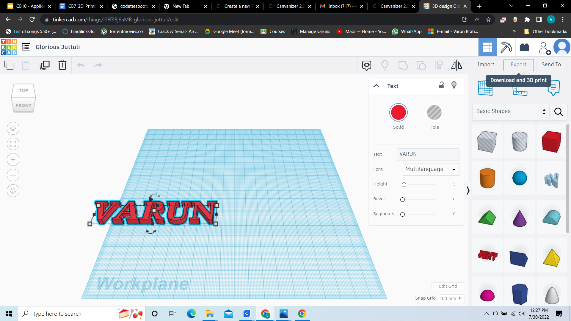
Then we go to export - stl
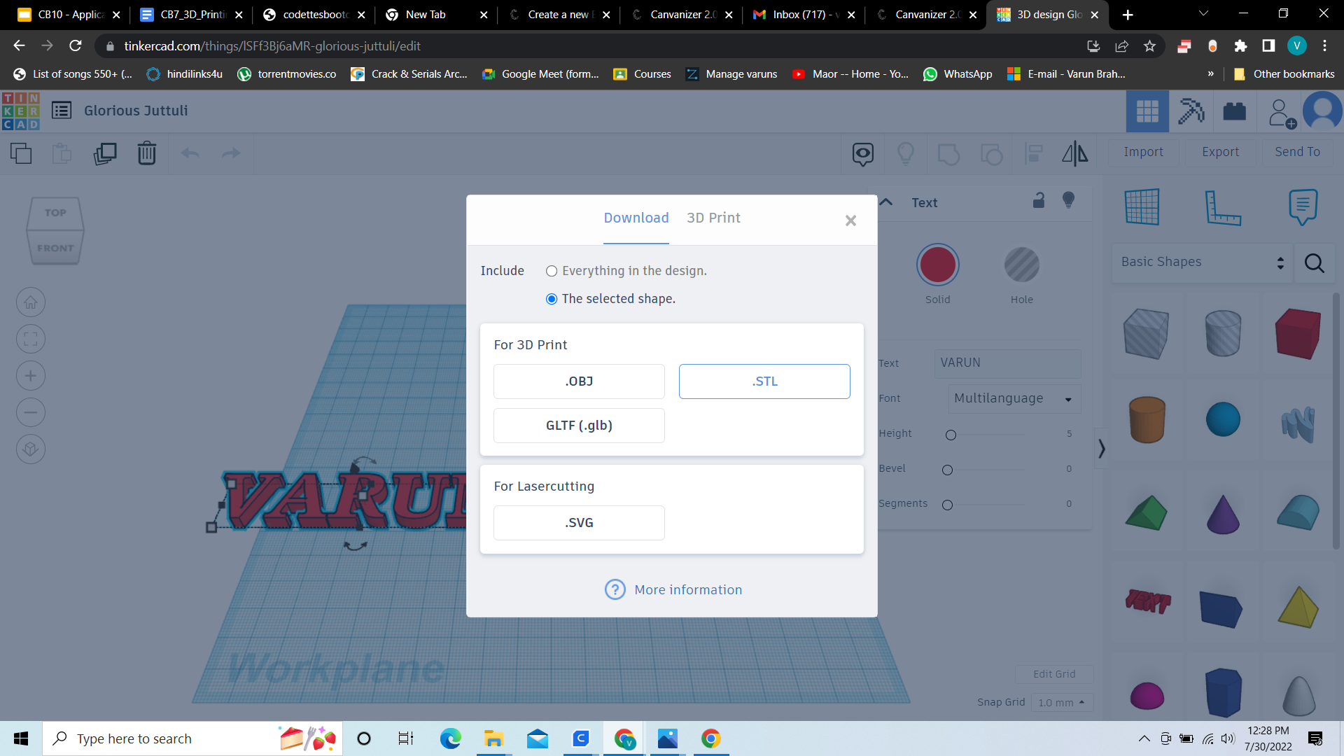
And save the file as an stl
7.3 G-Code
G-Code is the language that the printer understands, it’s basically just coordinates for the printer nozzle, so it knows where to and what to do, with some more info
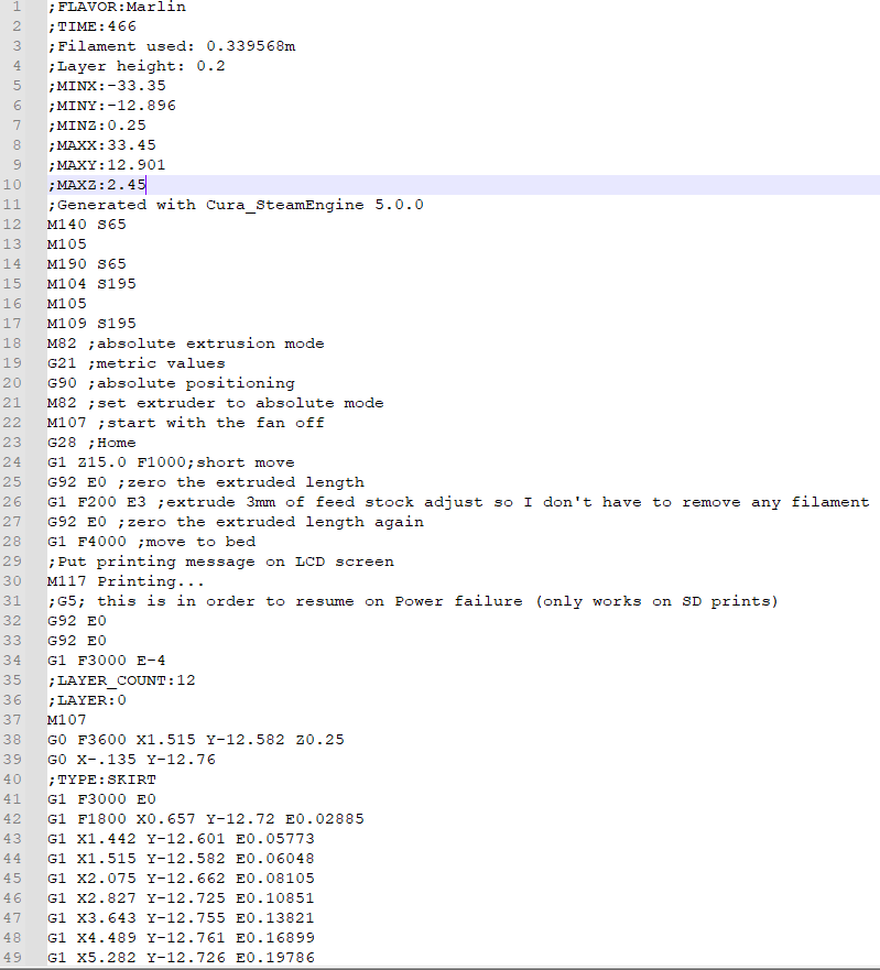
Here we see the time, the amount of filament used, the min and max in all the axes and some more info after that we see the coordinates in the different axes
Okay next step is stl to gcode
We can get the stl from tinkercad, when we design and we have to convert it to gcode for the printer
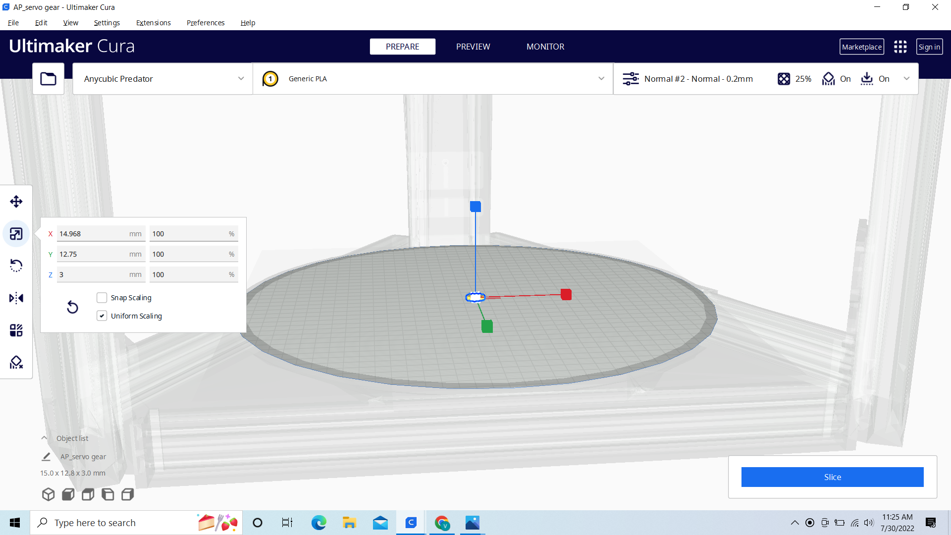
Okay First we have to load an stl file. WE go to File->Open File(s) 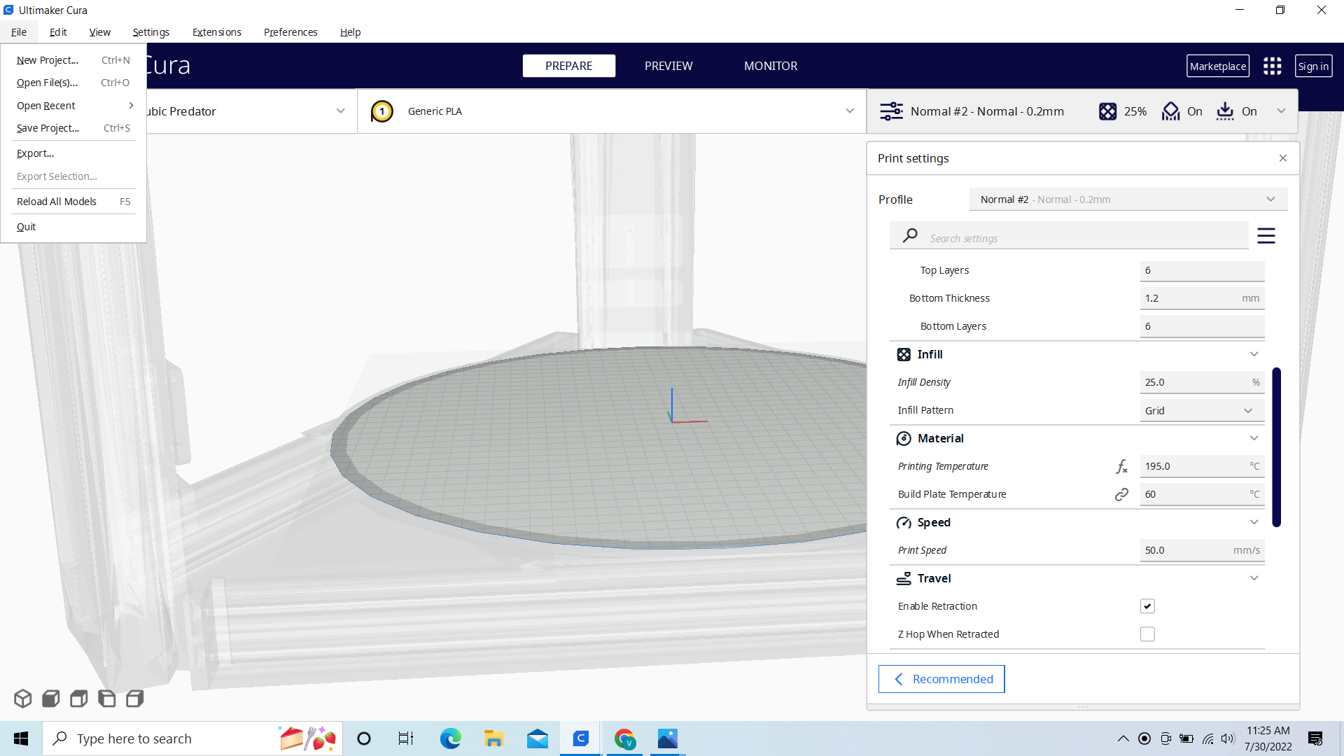 Now that our file is open. We have to scale our print to 104%
And then lay it flat.
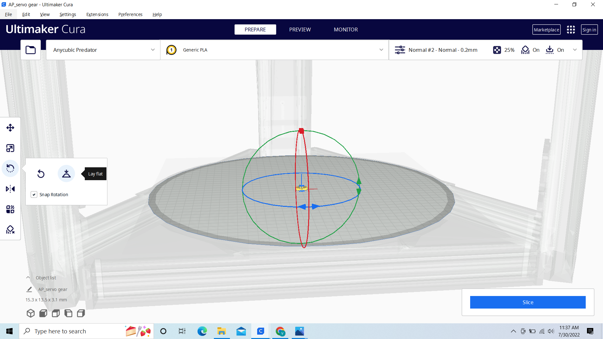
And then slice it. Now We have the amount of time it’s gonna take and the amount of grams of the filament.
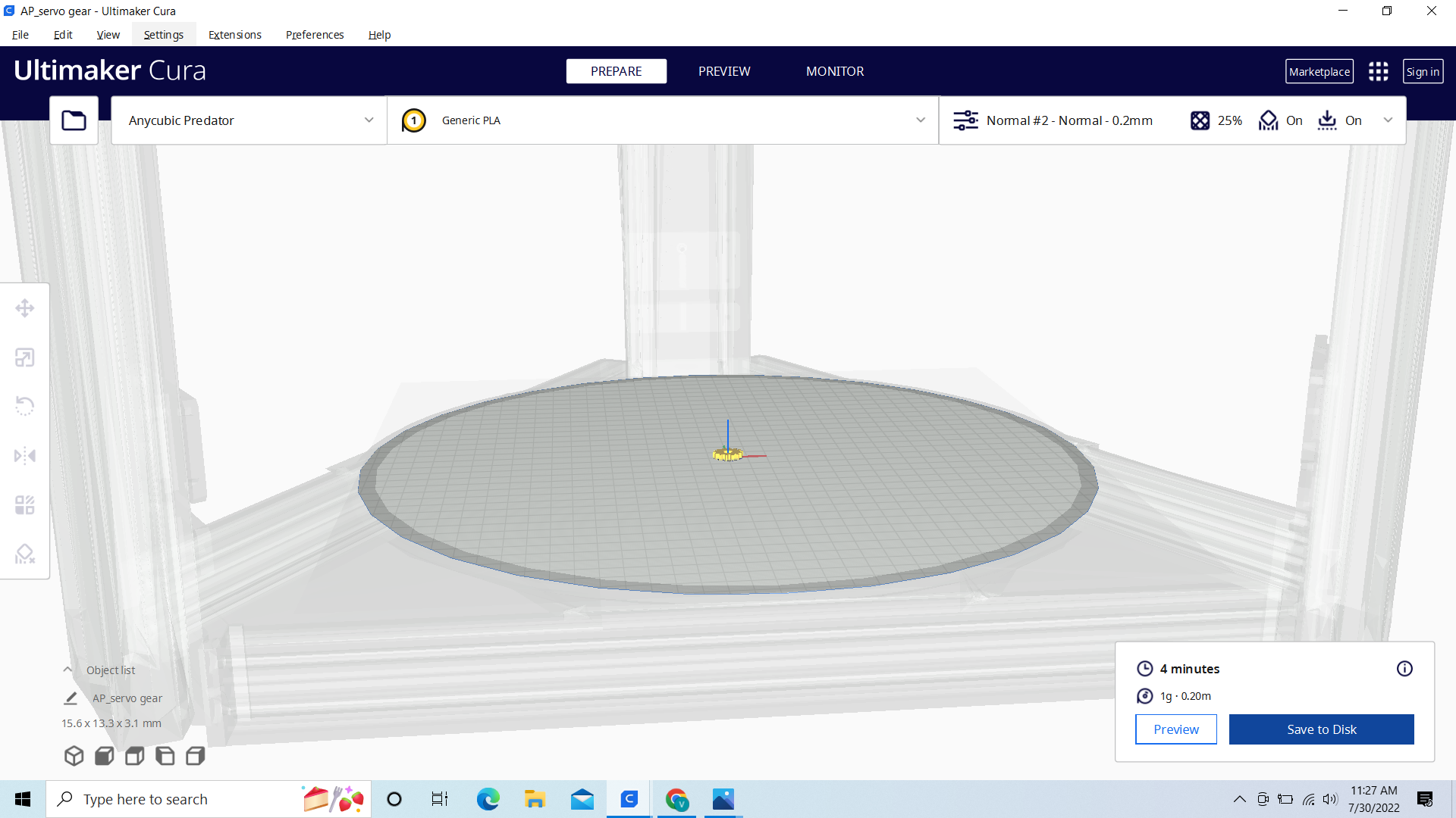

And now we have to save it as G-code. We click on Save to Disk and then enter the name
Now we can put it on the sd-card and print it. That’s for next time
7.4 Printing
Chapter 3. Business Model Canvas, Pitch & Poster
=========================================
3.1 Objectives
Wk 1
-
Setup your BMC for final project
-
Setup Pitch Deck
-
Create project poster
-
Add Screenshots and description of the process of creation.
-
Describe the design & programming steps
-
Screenshots or video of your Prototype/app working
-
Describe any errors or problems with the process and how you fixed them.
-
Include all the files you created for download.
3.2 Setup project BMC
What is BMC ?
The Business Model Canvas is a template used for developing newand documenting existing ones. It offers a visual chart with elements describing a firm’s or product’s , infrastructure, customers, and finances, assisting businesses to align their activities by illustrating potential trade-offs.
Canvas were initially proposed in 2005 by Alexander Osterwalder
In other words its your whole business plan on 1 sheet of paper
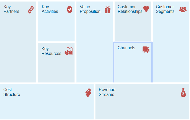
Value proposition: What do u have to offer, What’s so special about your product that the others dont have.
Ex: Quick response, delivery till home or repairs till home
Customer Segments: Your target audience, Who are the people u are selling to.
Ex: Schools, Hotels but also people with covid for example
Channels: How are u gonna reach your customers, ads and where are you going to place those ads,
Ex: Facebook
Customer relationships: Make a platform so your customers always come back to you.
Ex: custom coding
Key resources: The things you need to start your product.
Ex: Tools, Place to work, if u have many workers a bus for example
Key activities: What are do things u need to do, before your product hits the market
Ex: Make your own code or platform
Key partners: The less the better. Your partners in the product
Ex: Telesur
Cost structure: everything on the key side
Revenue stream: everything on the customer side
My Progress
My canvas: https://next.canvanizer.com/canvas/iYxVgoqjYPIHP
So now i am still playing with canvanizer, So i just put for value a submarine with a service and don’t mind the customer segments
I presented my bmc and got feedback
Value:
-
Different models
-
Sensors
-
enviorment
-
Location estimate
-
Lidar
Customer relationships:
-
A webapp
-
Custom parts
Channels:
-
A website
-
Stores
Customer Segments:
-
Kids
-
Researchers
3.3 Setup project PitchDeck
3.4 Project poster
Please use HEADINGS and create some structure in your documentation
Files & Downloads
Containing:
Chapter 4: Freecad ==================
4.1 Installing freecad and inkscape
 Just run the freecad installer and click through it
 Next run the inkscape installer and click through it
4.2 Creating a hole in Freecad
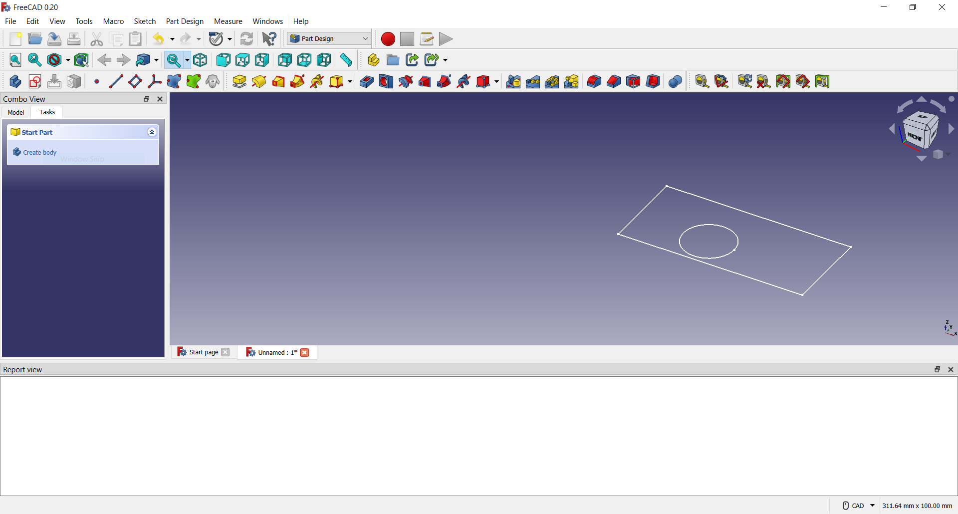
First we create a new object
 Create a new object
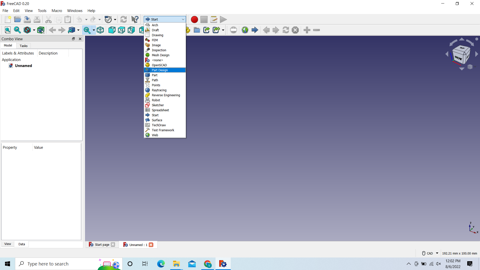 Instead of start-> Go to Part Design
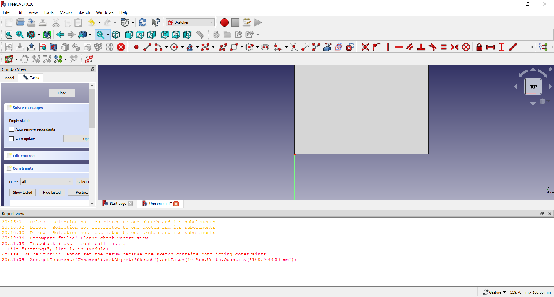
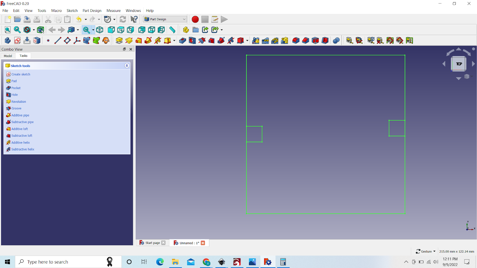
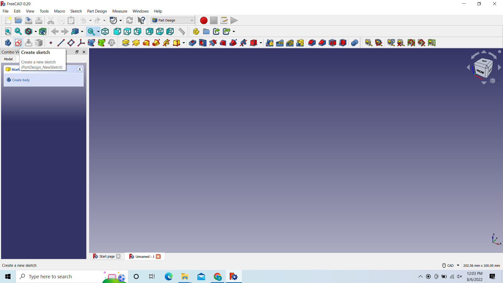 Click on Create sketch
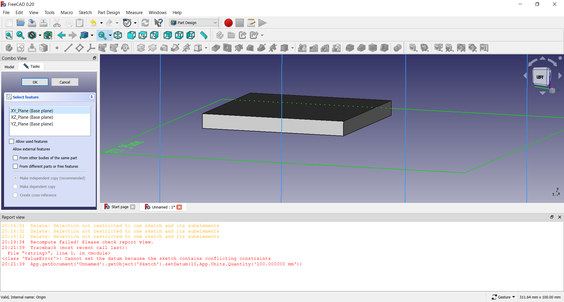
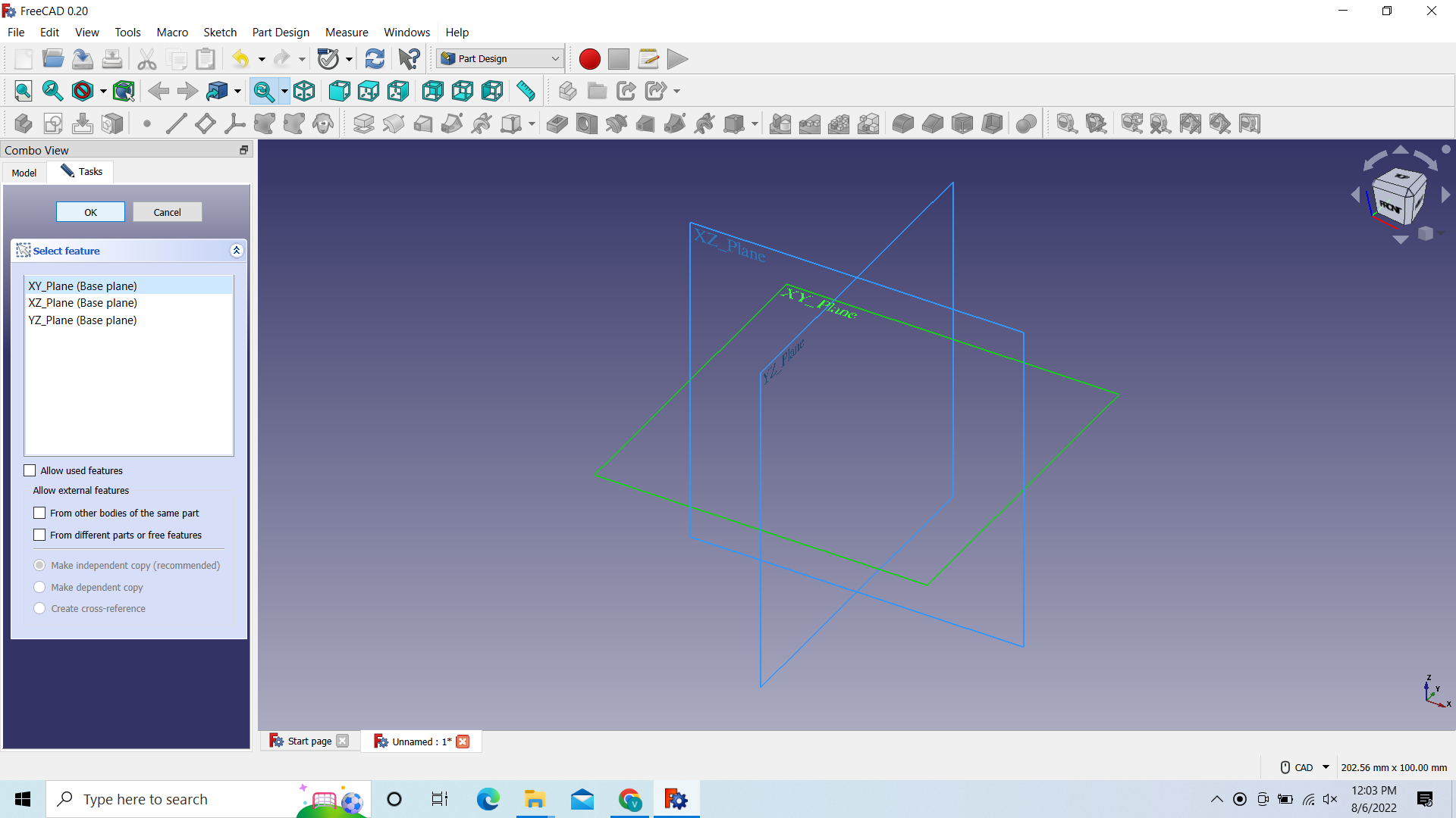 Select XY_Plate and click on OK
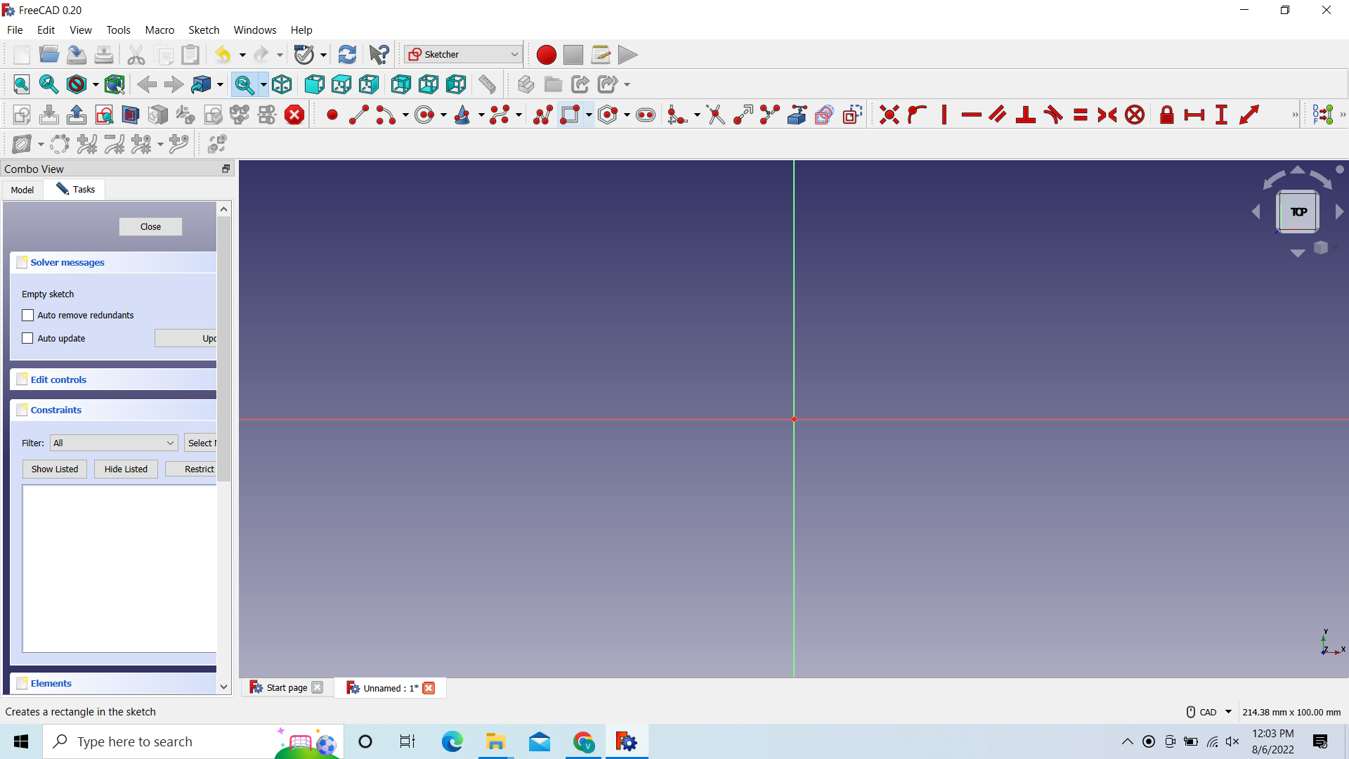 Go to Create Rectangle and click on it
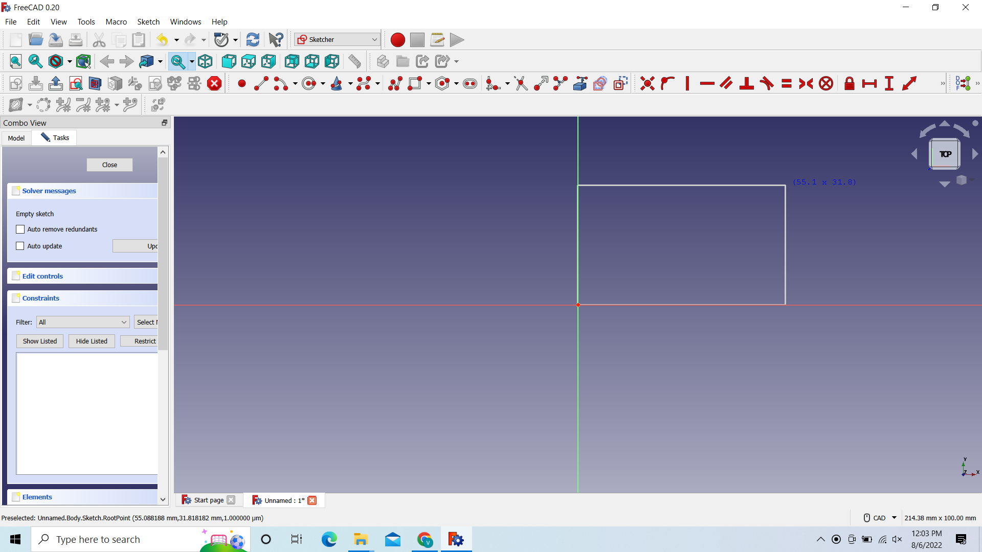 And then Draw the rectangle
After that we need to adjust the length and width of the rectangle to 100mm
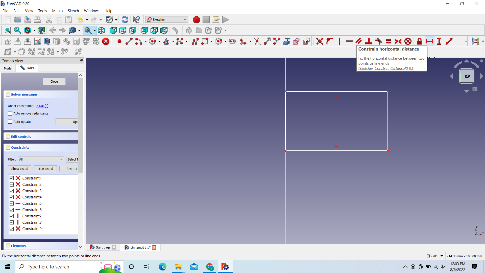 We first go to “Contain horizontal distance”
And then click on the horizontal side
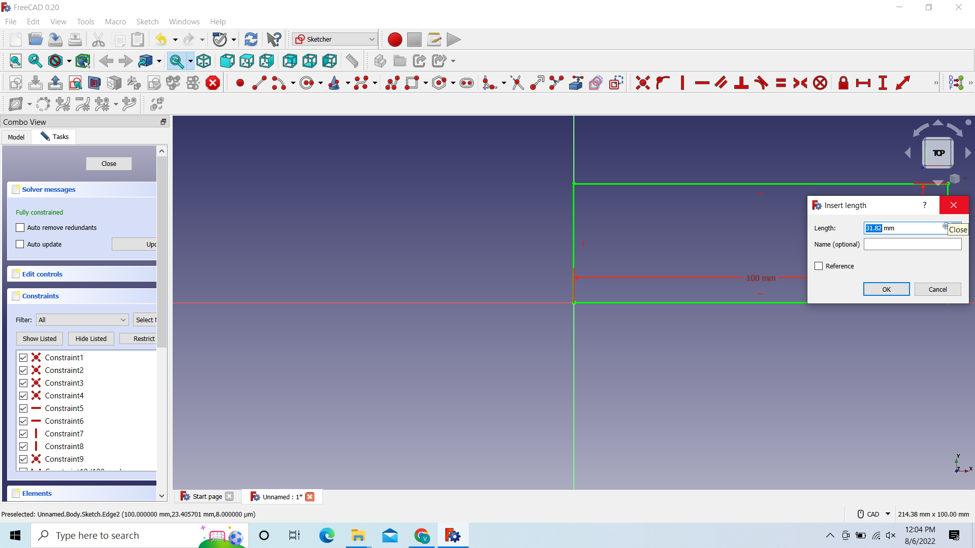 then adjust it to 100
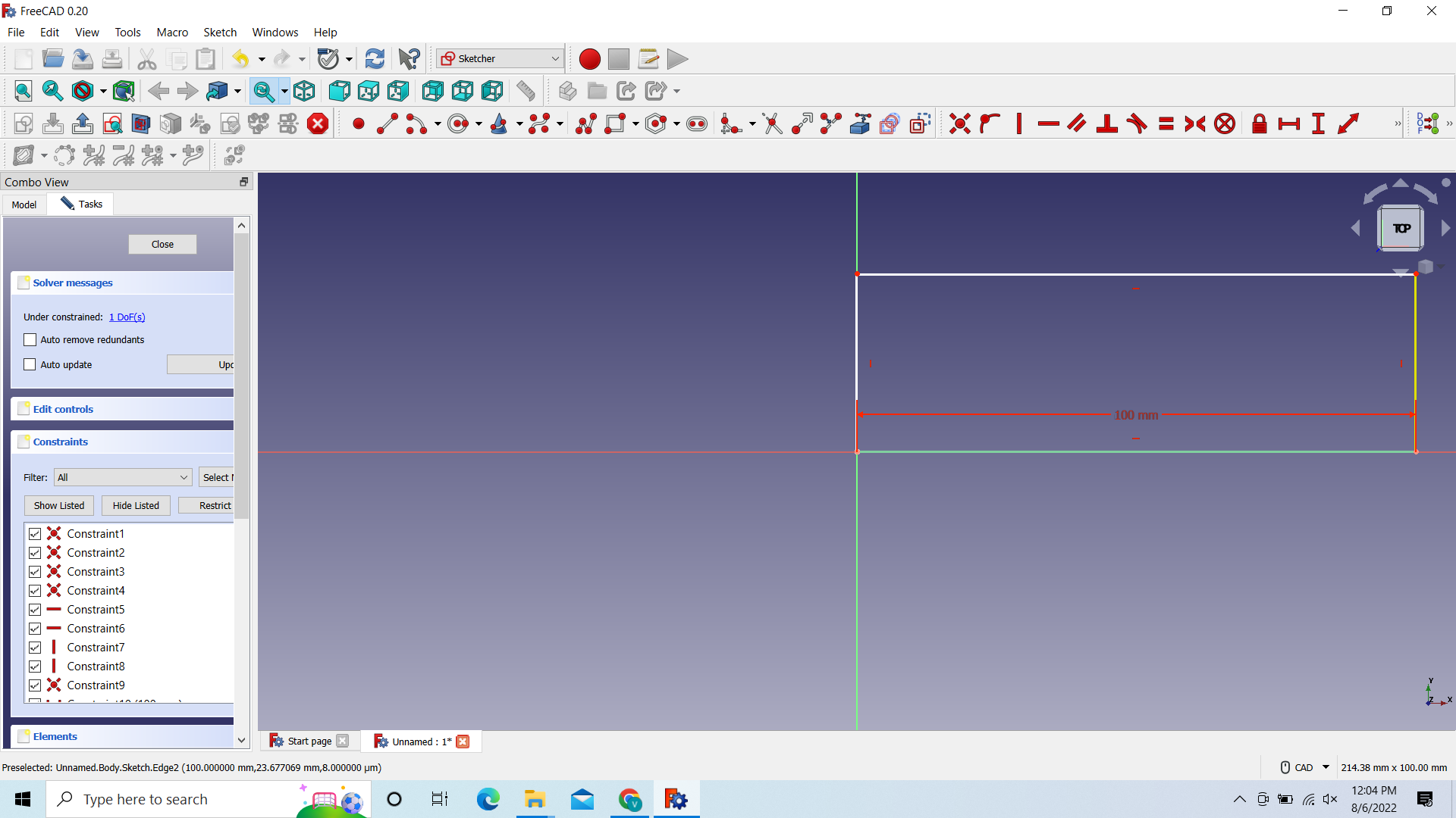 the vertical side
And then adjust the width to 100mm
the vertical side
And then adjust the width to 100mm
–till here for creating a pocket—
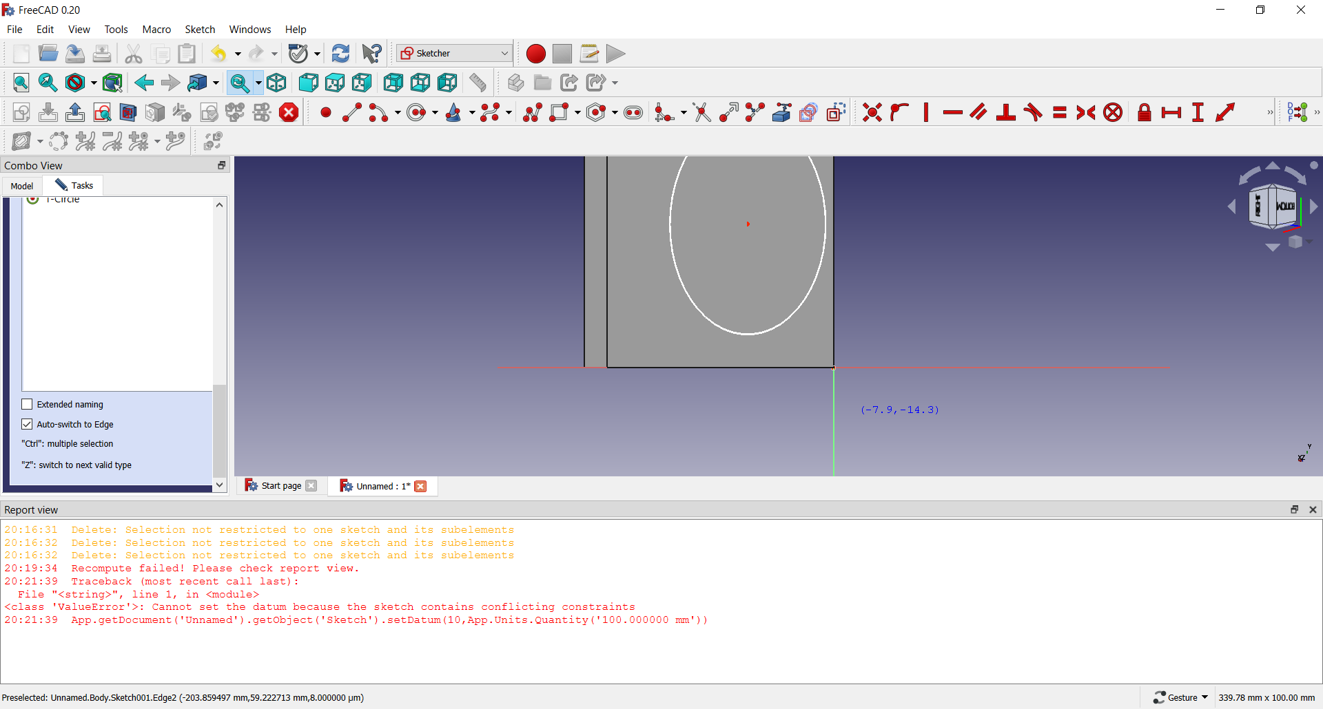
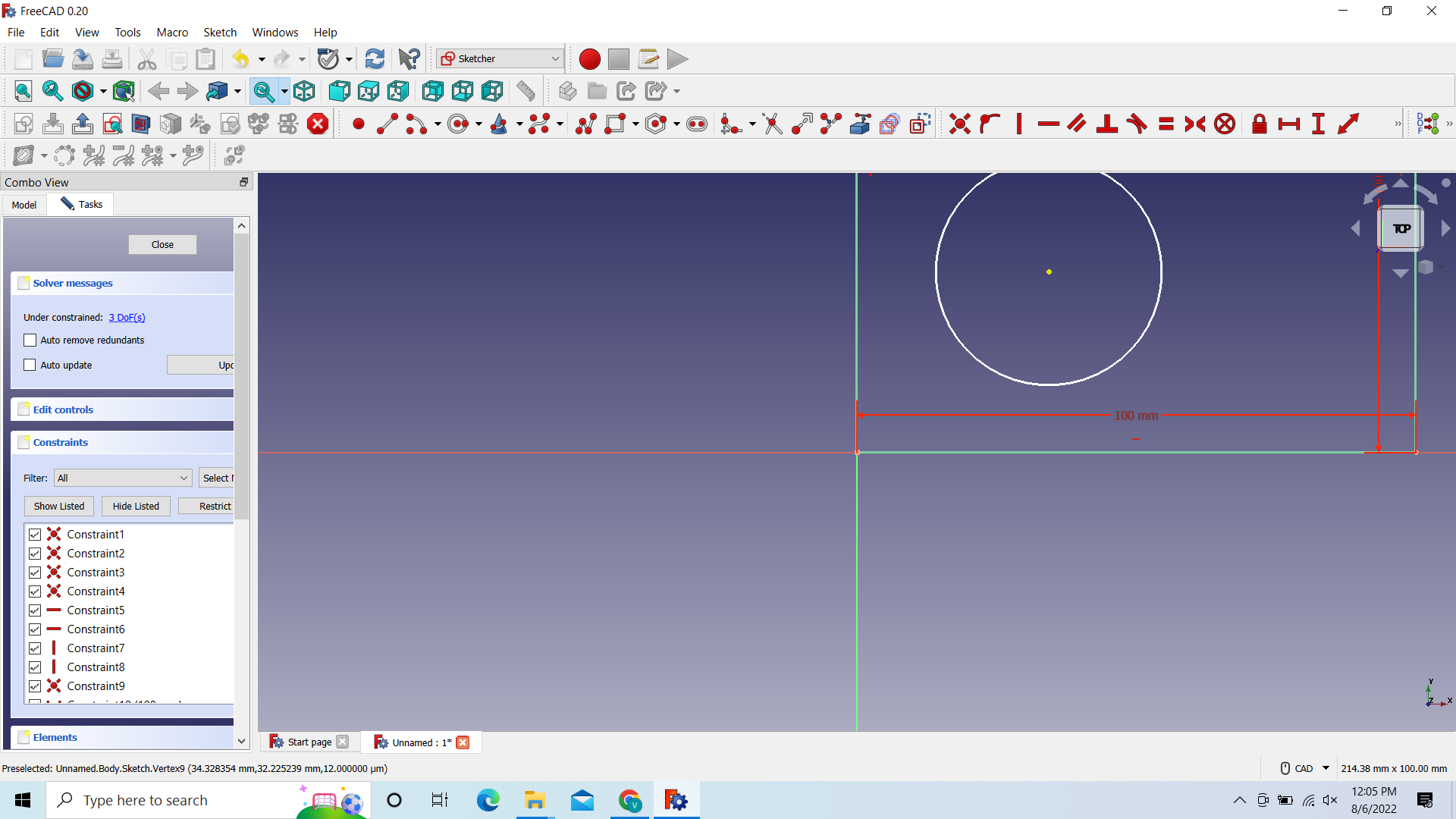 After that choose the circle and draw one
After that click on close in the Task
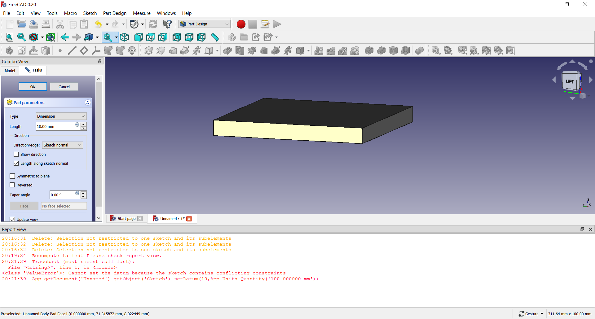
 After u click on pad there will be a solid layer
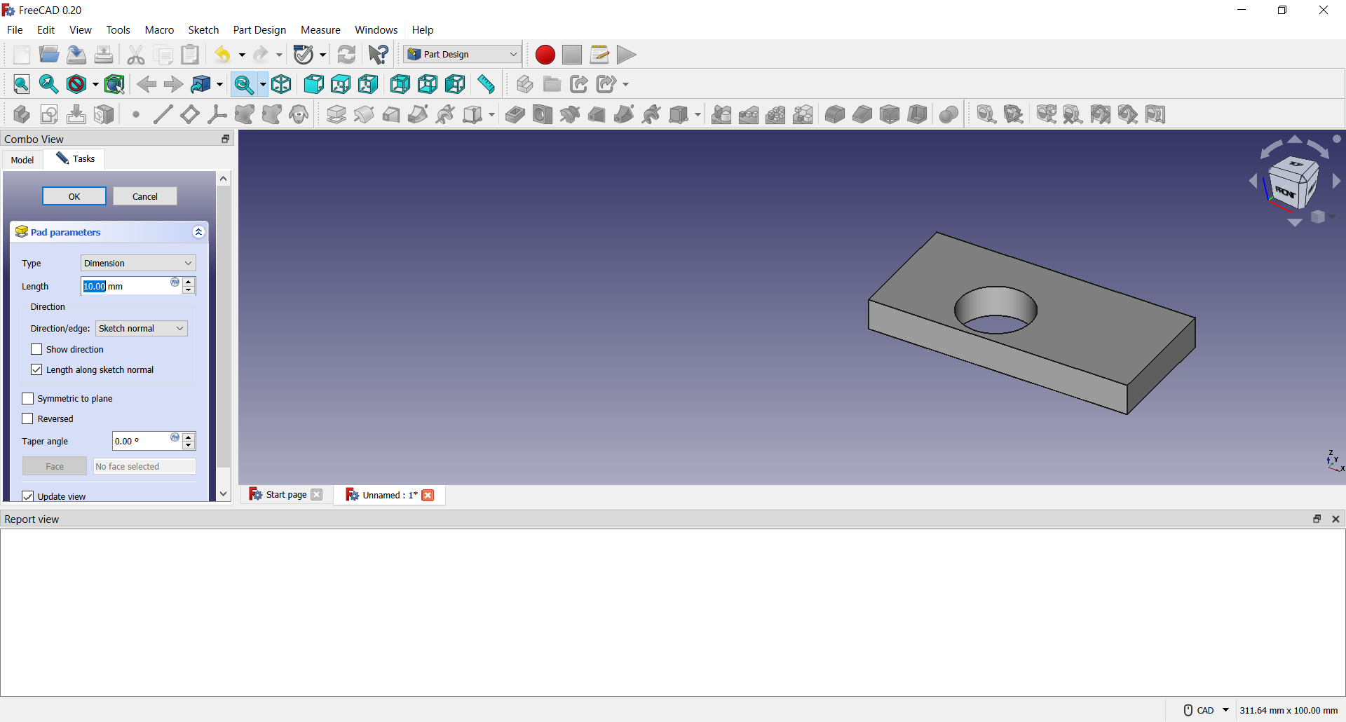 Like this and now you also have a hole through it
4.3 Creating a pocket
You can follow the last documentation and its marked till where
You just click close and when back u can just click on pad
 U will have something like this, you can click ok, Select the top and after that you can click on create sketch again
 And you can select the XY_Plane
 After that you will see your solid design and you can draw a circle on it, for more info on that check chapter 4.2
Note: The circle may come on the opposite side, but dont worry, just draw it and turn your design
 Here i already have the circle and i turned my design
You can click on close from here
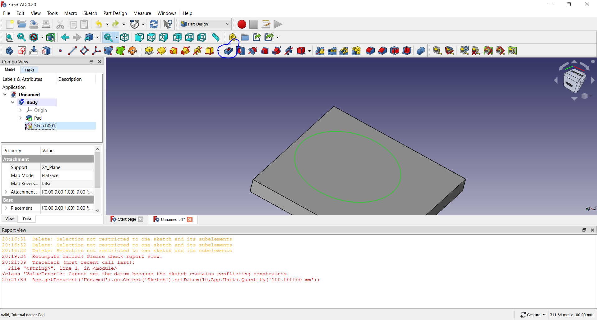 And now you can click on pocket and just close it from the task
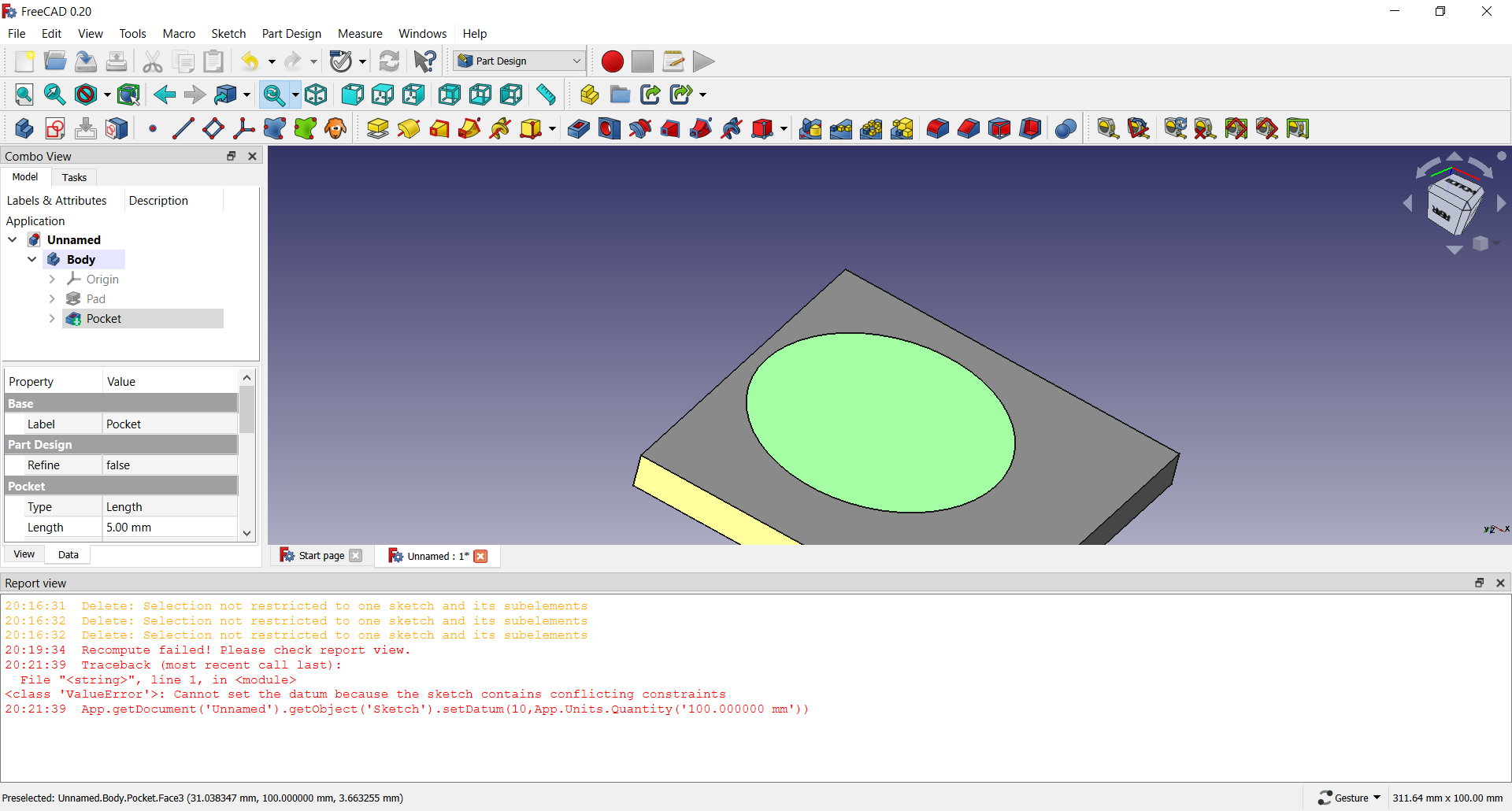 The select the circle in the middle so it becomes a different color and click on pocket again
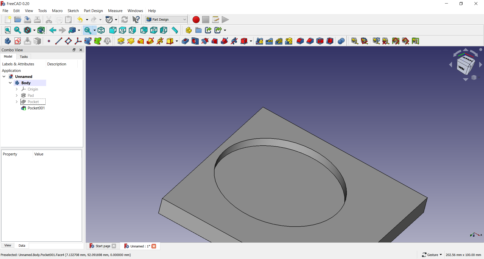 Then you are left with something like this, you can adjust the parameters if u want, its on the left side in the combo view in either Model or Task
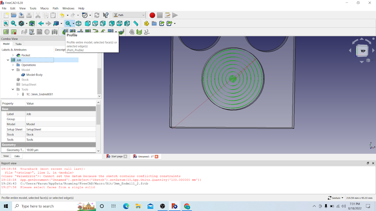
4.4 Creating the holes
First we created a object with 2 holes and 1 pocket
Parameters i used are: 100mm100mm10mm
Check the previous paragraphs for that
After we have that

U should have a object like this and then go and select Path

After you selected path go and click on job
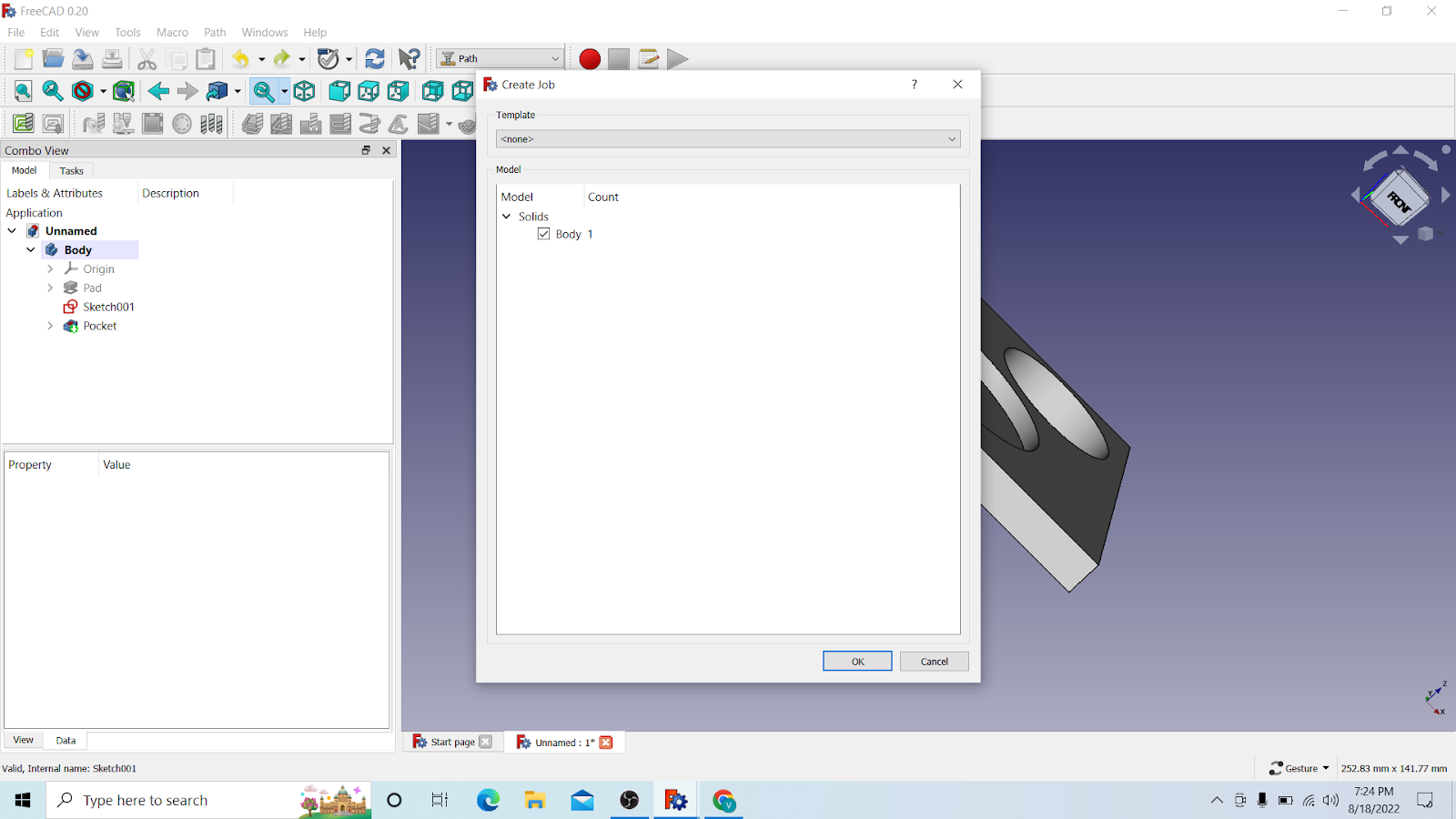
I select body 1, but i dont think its necessary and then just click on OK

After that you will see that the purple bubble is on the bottom, you need to bring it to the top, So u have to precisely select the corner above it, in the picture you can see the corner is yellow(a small dot)

After you have selected the corner, go to Set Orgin and click on it and the click OK

After that go to ur body and press the space bar to hide it

After that go to Model Body and press the space bar to activate it
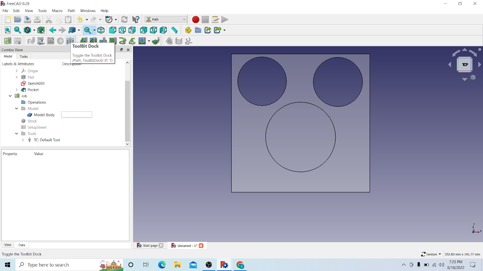
You will see something like this, after that click on ToolBit Dock
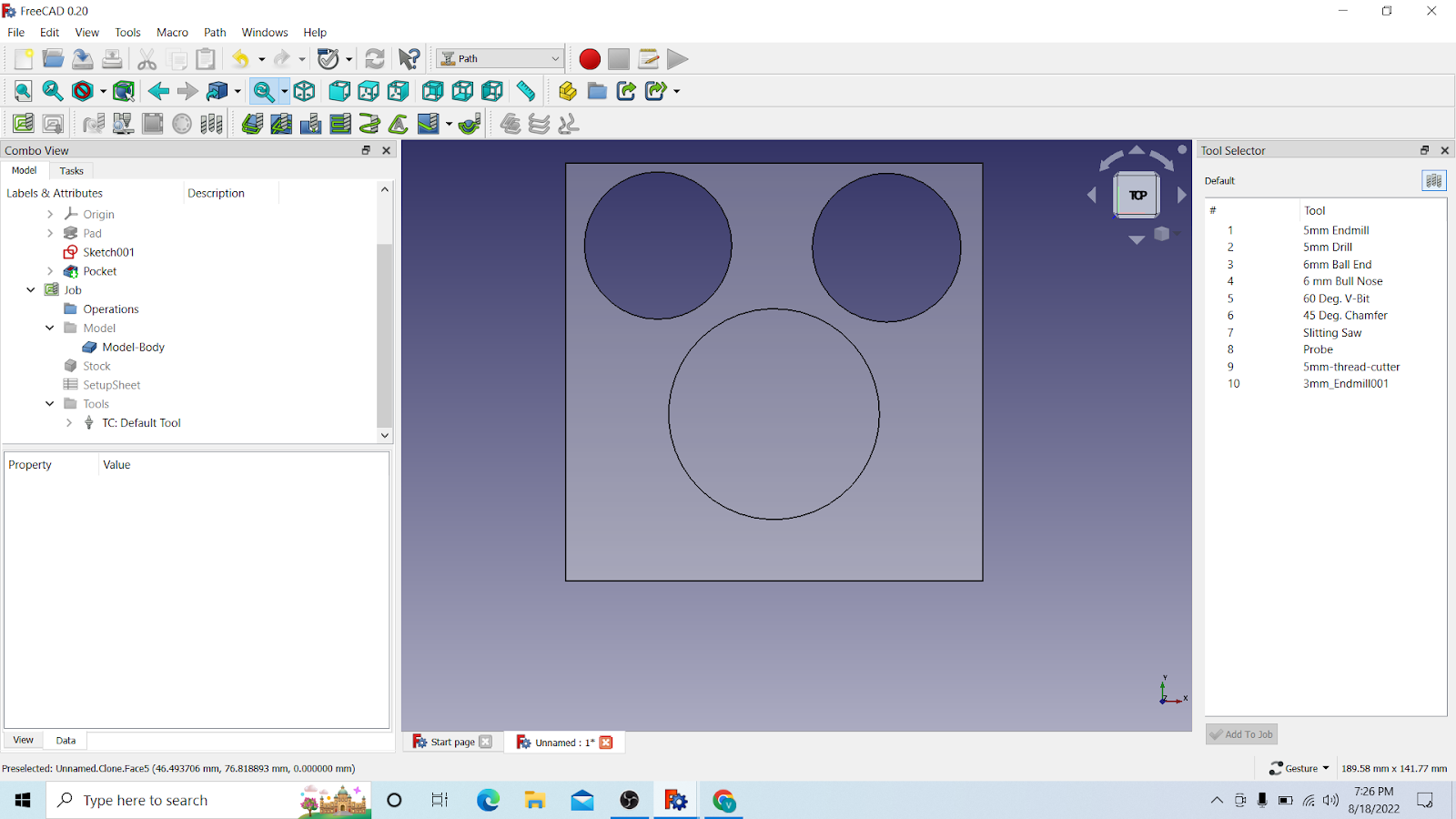

You will see something like this then, click on Create Toolbit

Select endmill and click on open
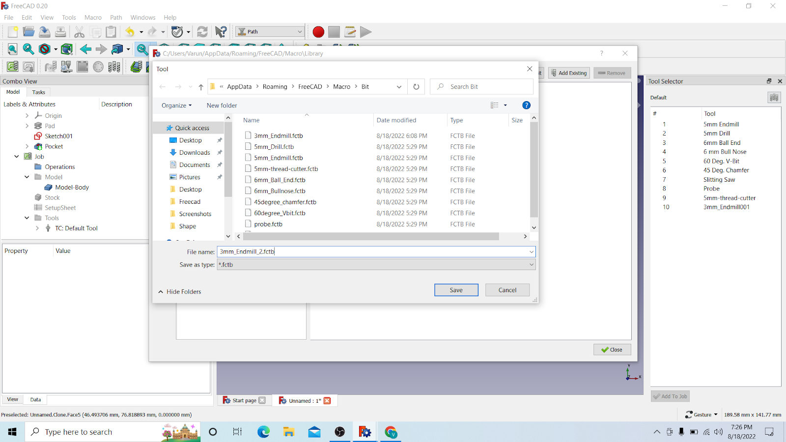
Here just name it something, i would recommend the bitsize_endmill.fctb
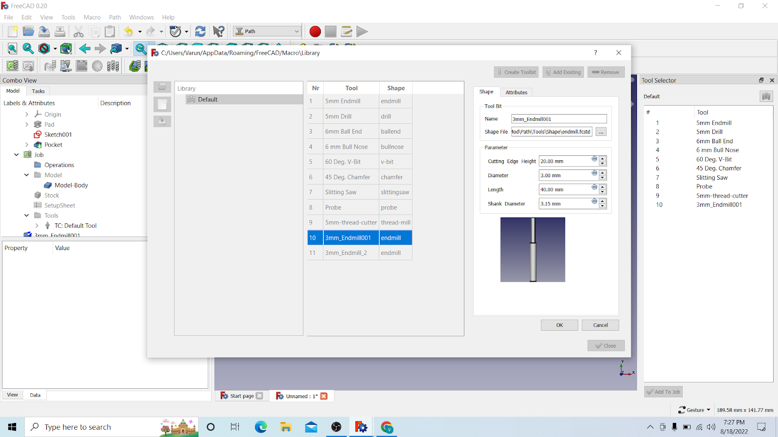
Then you will have it added, i opened here an old one of mine by double clicking on it, so i can see the parameters. These are the parameters for the 3mm drill bit
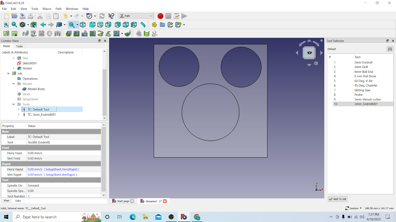
Then you will see it comes on the list on the right window, you can just select it and it will come on the left side, you can delete the default tool from there then
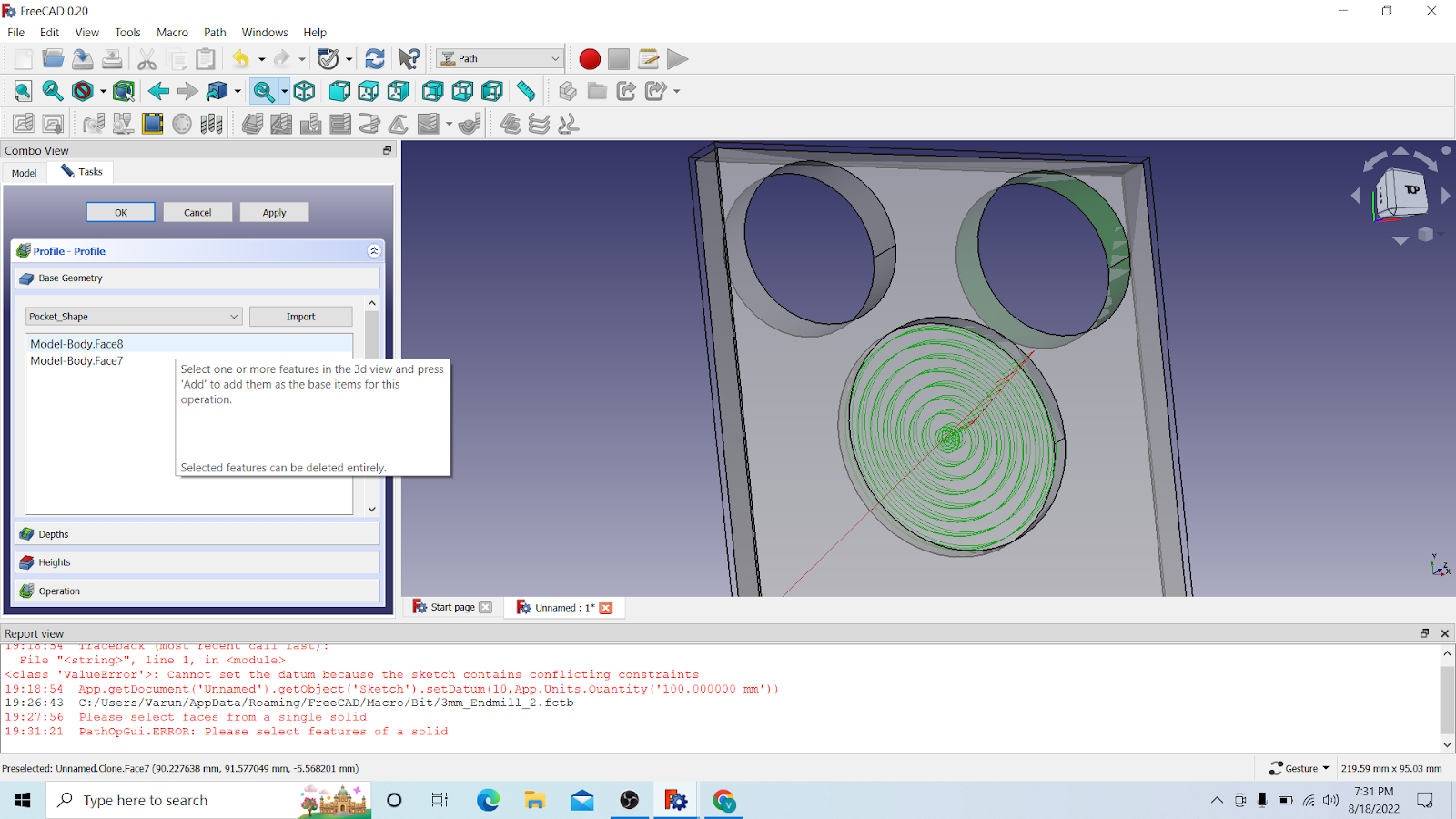
Now go to pocket shape
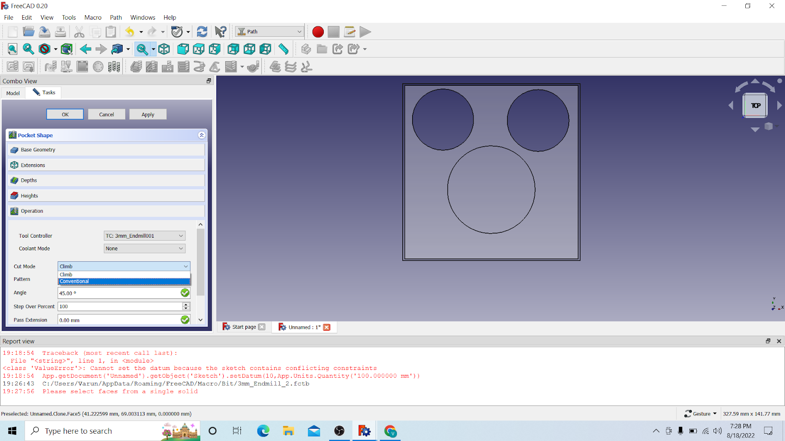
Here select cutmode: conventional

and pattern: offset

And check the box of use outline
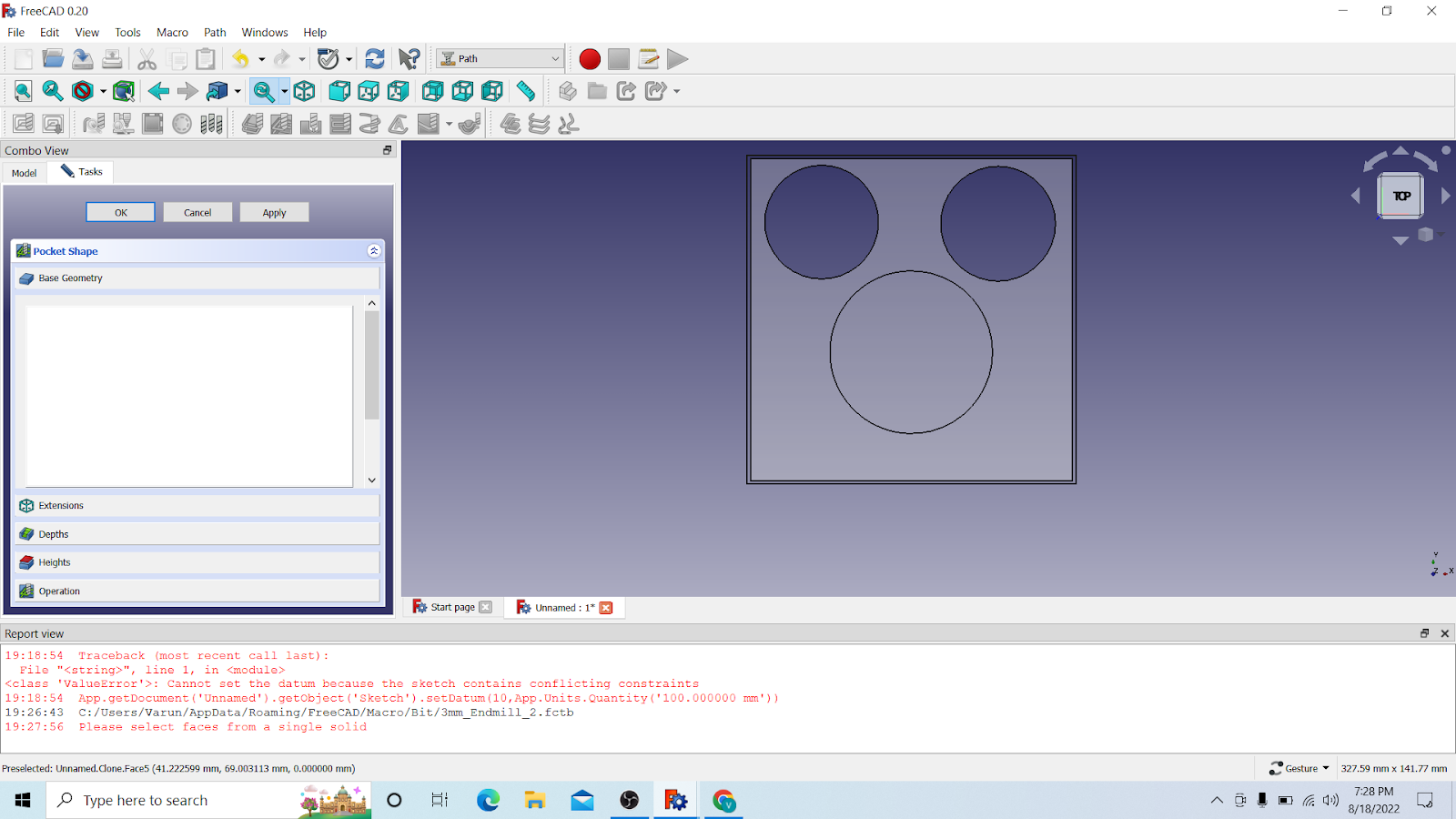
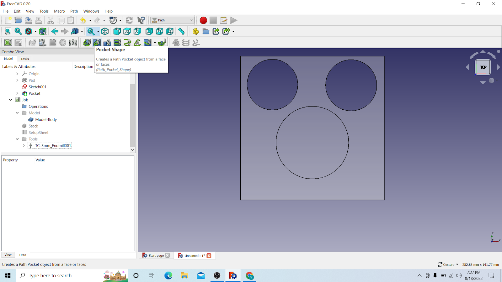
Then go to Base geometry
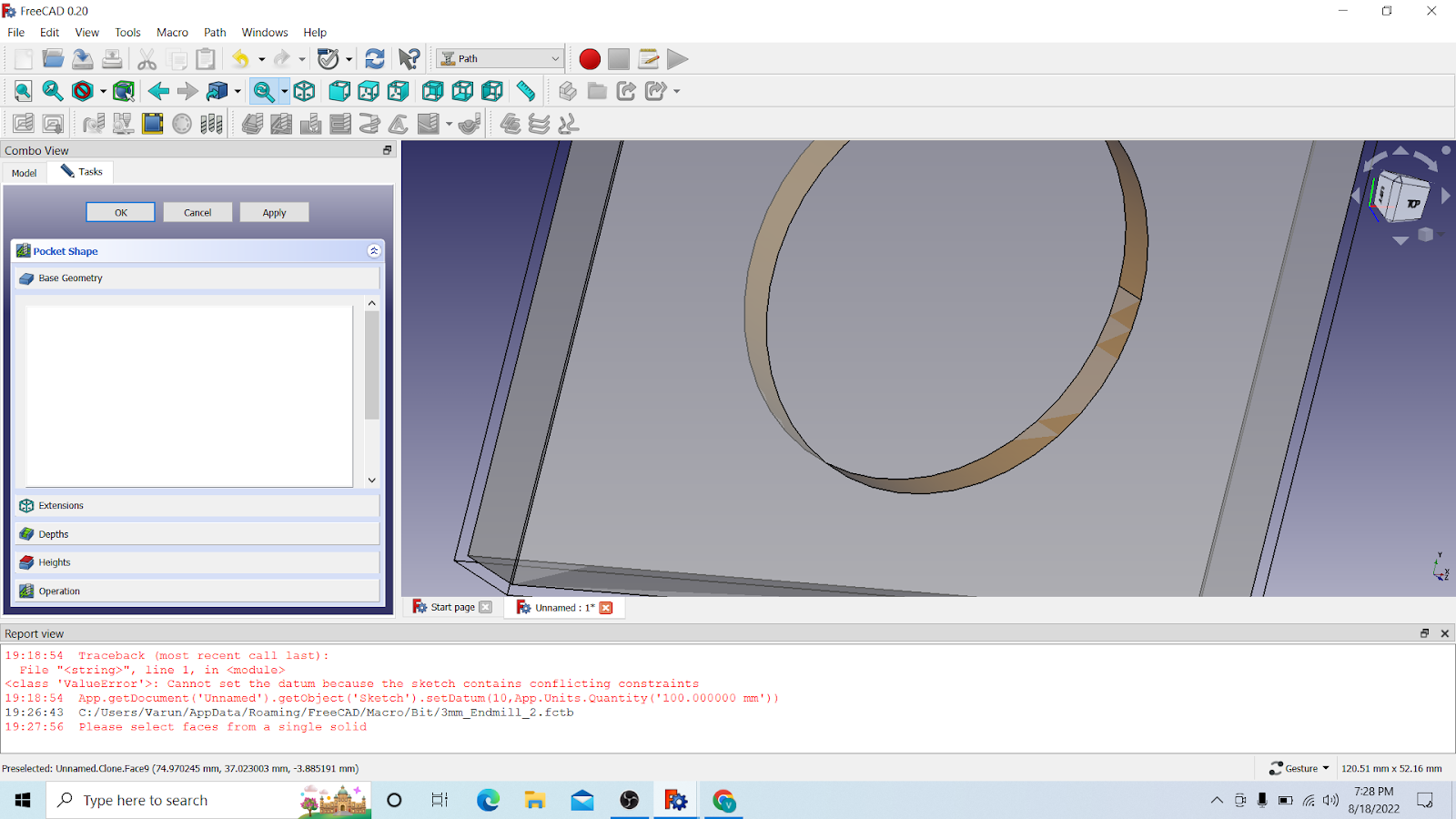
And select the inner edge of the pocket, like this

Look now it is green, then click on add
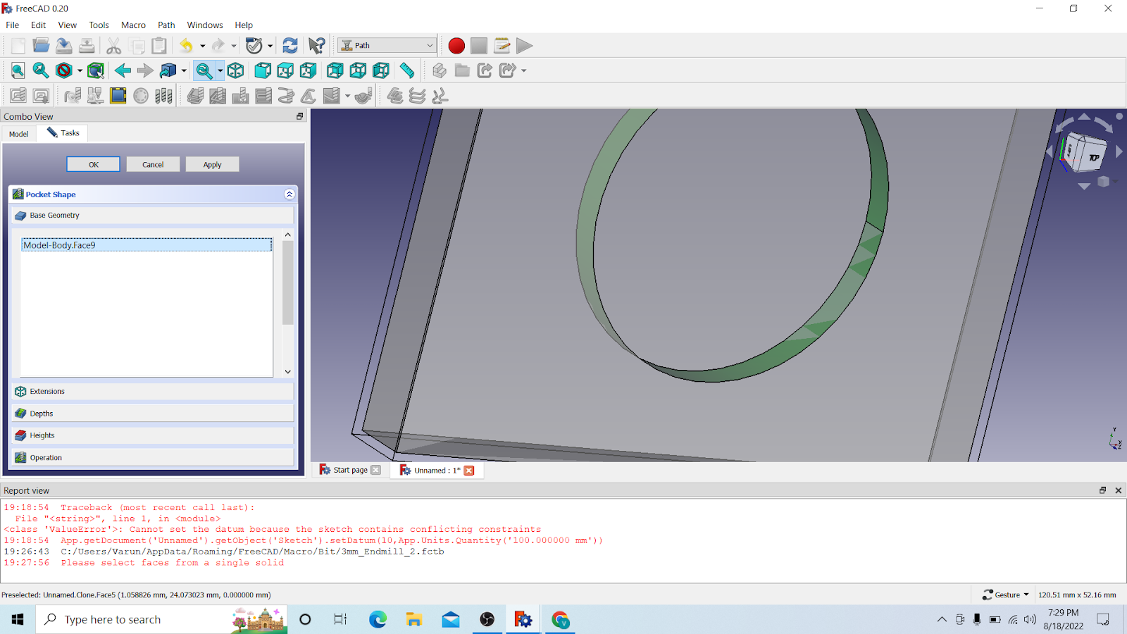
And now its added

Then go to depths. Here you also have to adjust the parameters.
Start depth: 0.00mm(standard)
Final depth: -5.00mm(pocket depth)
Step down: 1.5mm(half of your bit diameter)
After that click on apply and OK
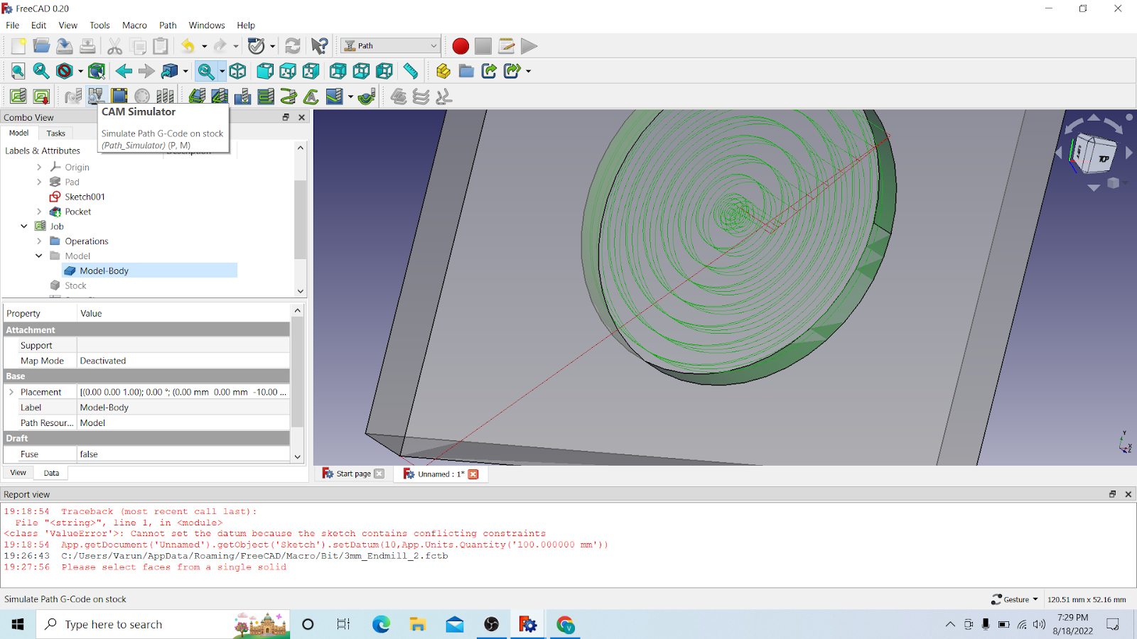
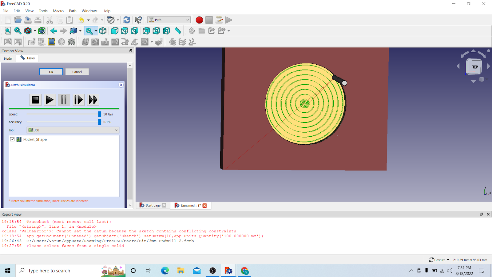
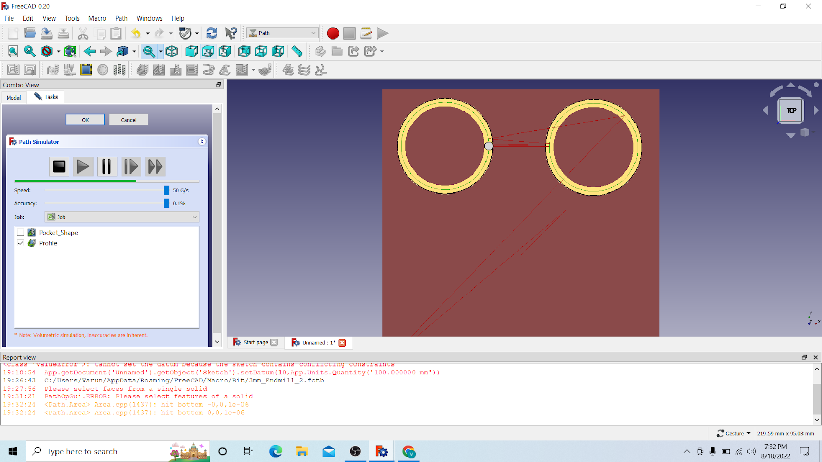
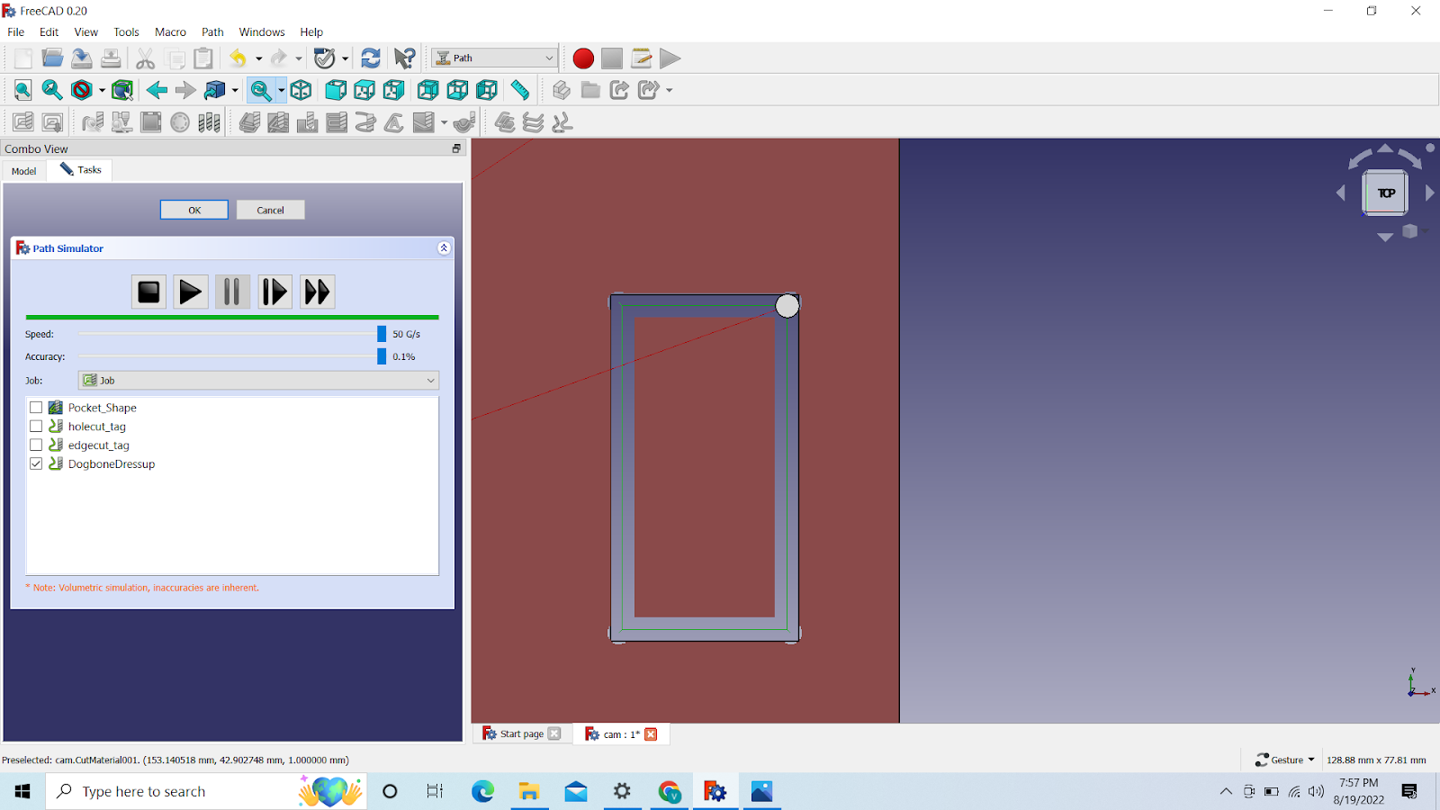
Then you can go to CAM Simulator

And then just click on play
Now the 2 holes, Click on Profile
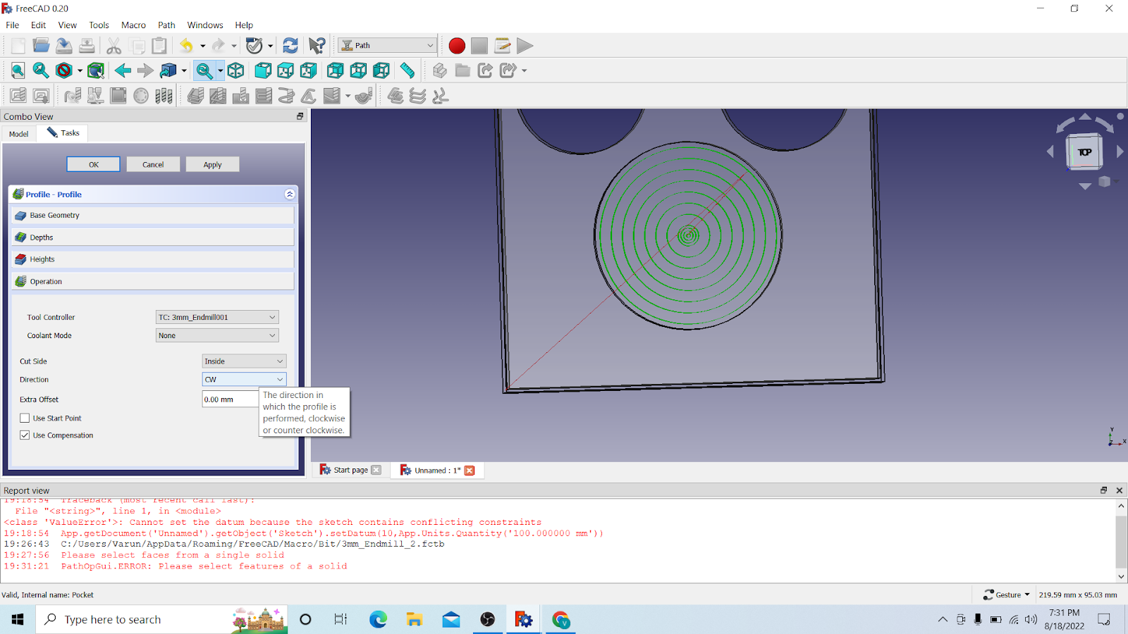
Then select inside
Once here you also have to select the inner edge of the circle and click on Add
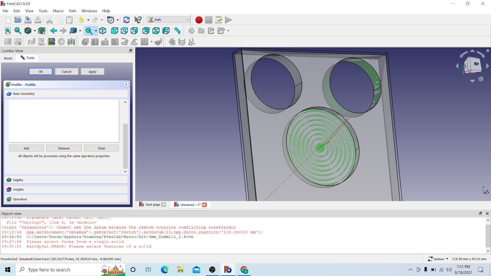
Now the second one, click on the inner edge and click on Add
Here you can see, both are added
Go the depth then and change the parameters again:
Start depth: 0.00mm
Final depth:-10.10mm(a bit more then your thickness +0.10mm)
Step down: 1.5mm(½ of your drill bit diameter)
Then just click on apply and OK
THen you can go to cam again but no unselect the Pocket_Show, so it only simulate drilling of the holes
If you have this then your almost done, i forgot a step

Double click on your drill bit

Hozin.Feed: 240.00mm/s
Vert.Feed:80.00mm/s
Spindle:10000
And click on OK
4.5 Cutting the outer edge
We will continue on the previous project of ours
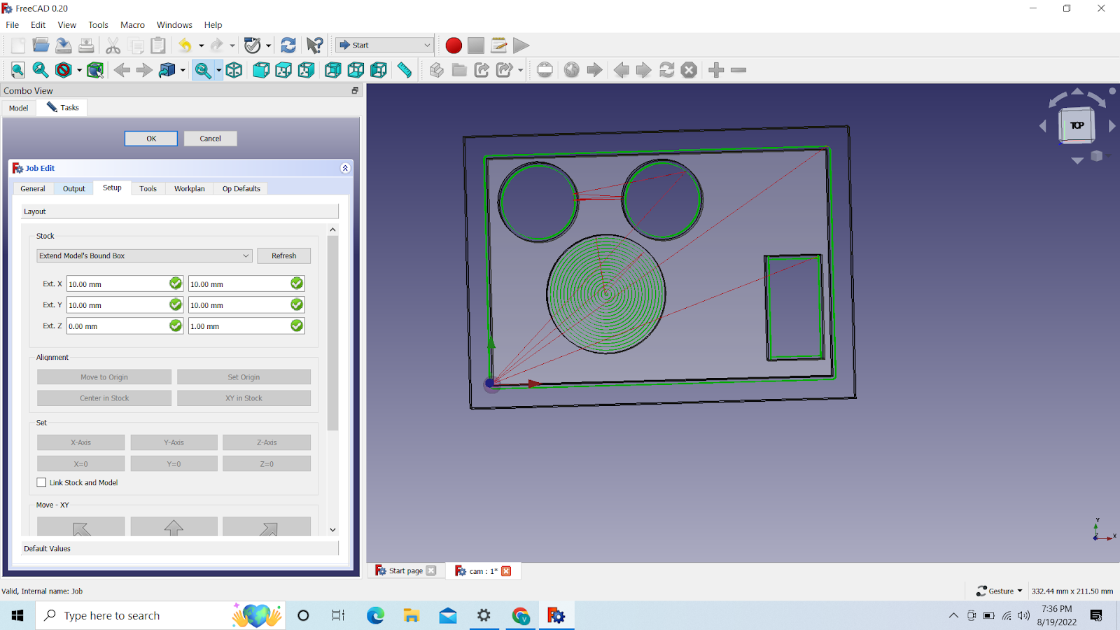
This should have been done the previous time but okay, Go to Job and change the X and Y to 10mm, Z Stays 0mm
Click on ok after that

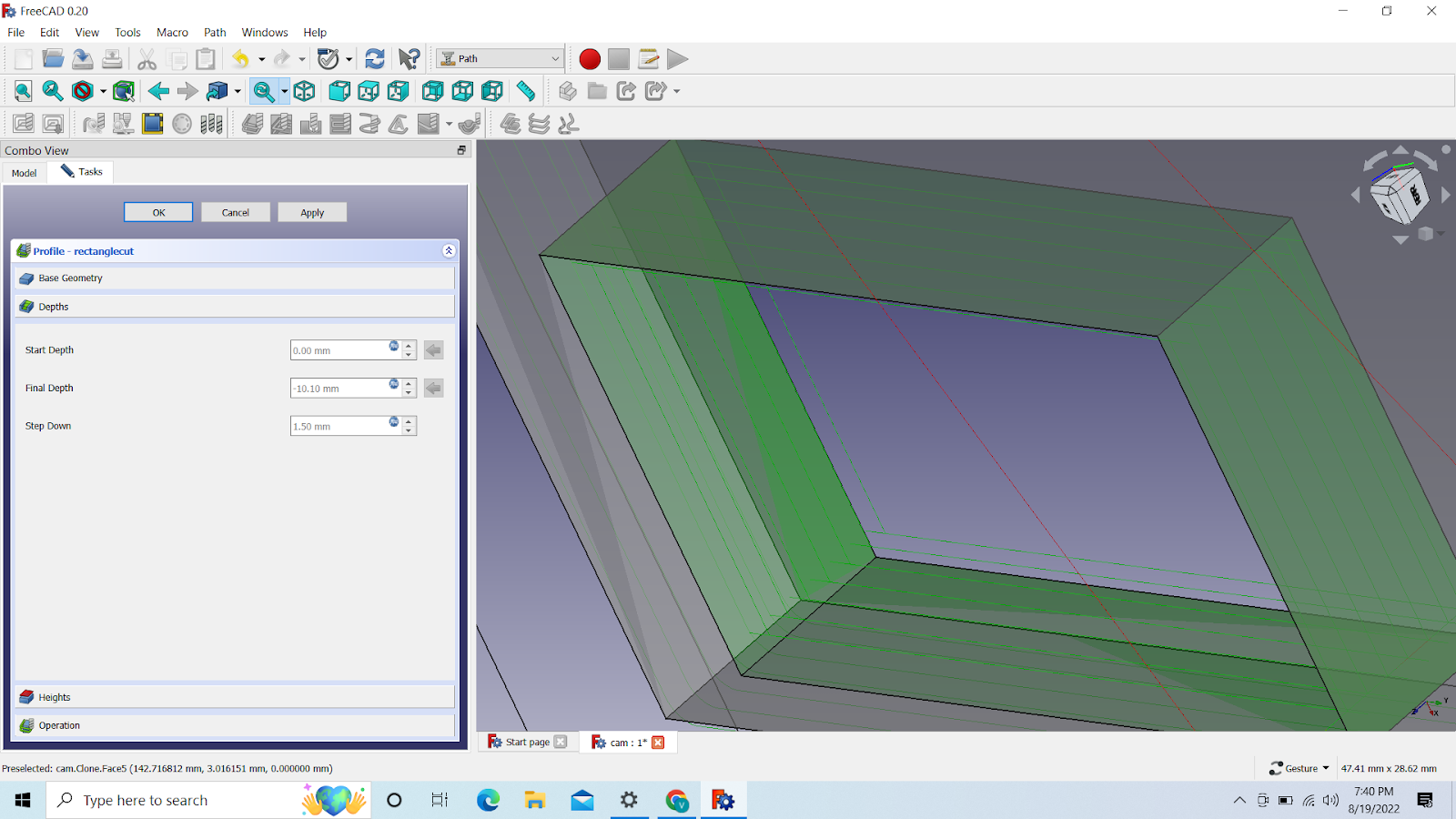
THen we create a new profile, and select the top of our base and add it

Then we go to depth and select these values
Start depth: 0mm
Final depth: -10.10mm
Step down: 1.5mm

And make sure its an outside cut
Now we have to add tags: What are tags ? to make sure the piece that we cut doesnt start to move around while we are cutting it
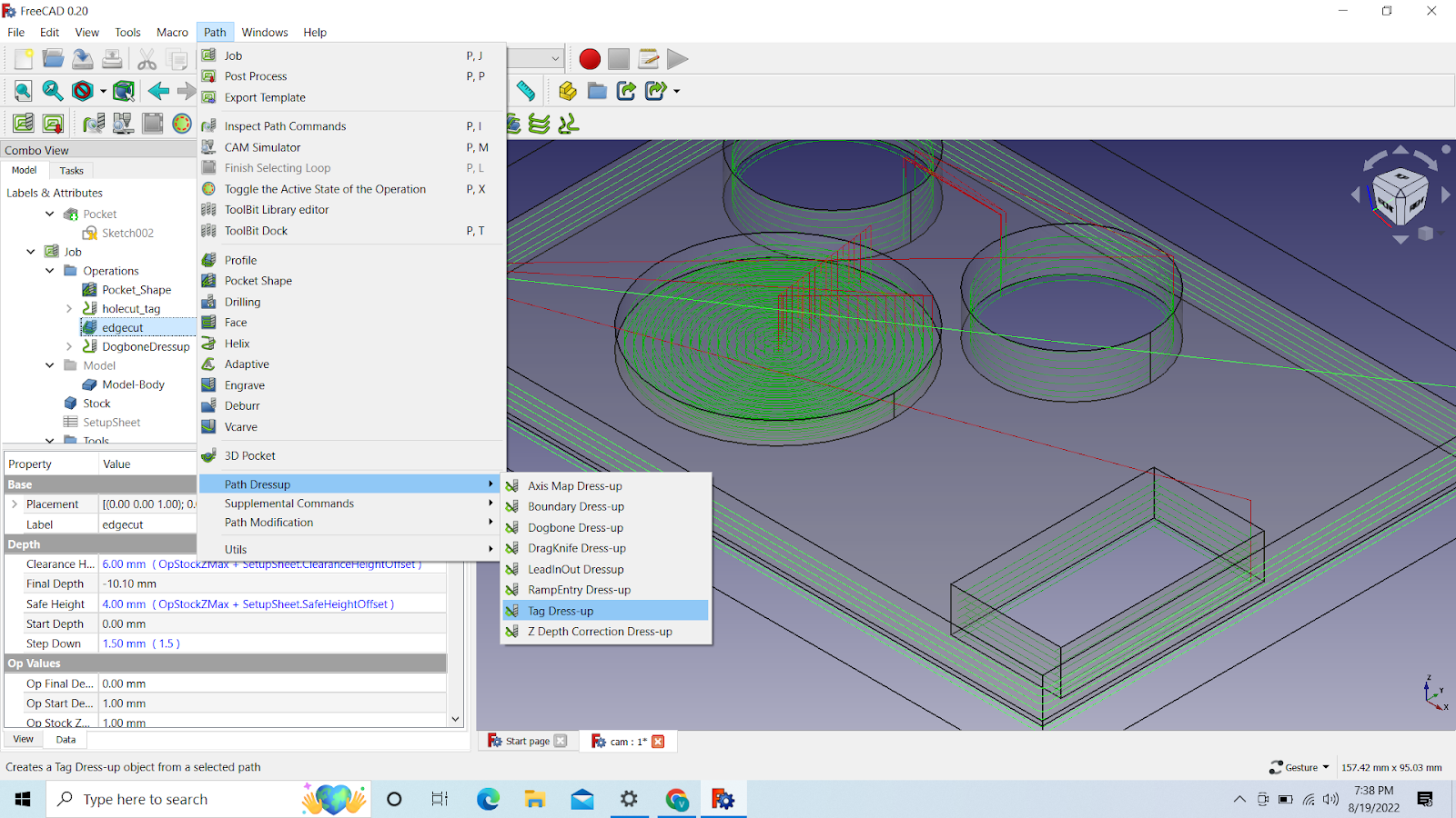
To add tags. Select the profile first then go to: PAth->Path Dressup->Tag Dress up
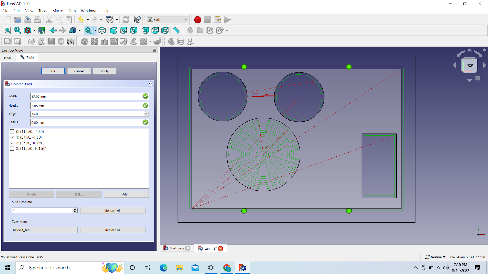
U will see the coordinated and the location of the tags then, you can adjust them if u wanna, but i am gonna leave them as they are

Then i am gonna simulate it and it should look something like this then
After that we wanted to try dogbone tags, So we created a rectangle hole and putted the tags in there
To create a rectangle check my previous documentation
I am gonna start with the profile for the rectangle

We have to select all the inner edges 1 by 1, and then add them
We go to depth
Starting depth: 0mm
Final depth: -10.10 mm
Step down: 1.5 mm

Make sure its an inside cut
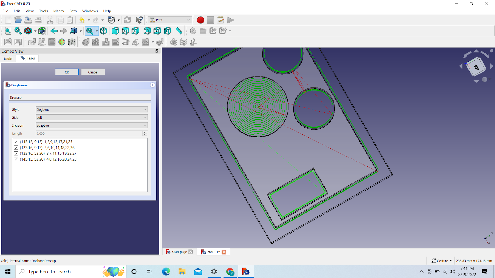
Then we select the rectangle profile and go to path->path dressup-> dogbone tag
Then we will see the coordinates, then we can go simulate it
The little bit in the outer edge is the dogbone
4.6 Design for the Laser
The laser doesnt use 3d design like the 3d printer or the stepcraft, So we need a 2d design for it, To make your own design we can use freecad
We just create a basic square with 2 holes(square) on the sides
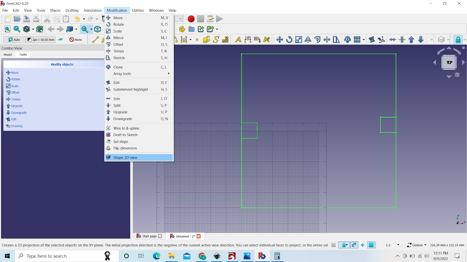

File->Export-> save as a Flattend SVG
After we have the design we need to CAM it
For that we can use inkscape
Makerspace
We can also use makerspace to design a box or something
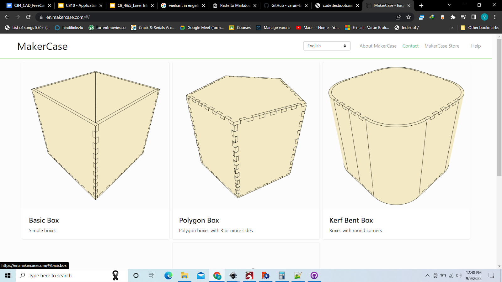
First we select the type of box, i will take basic box
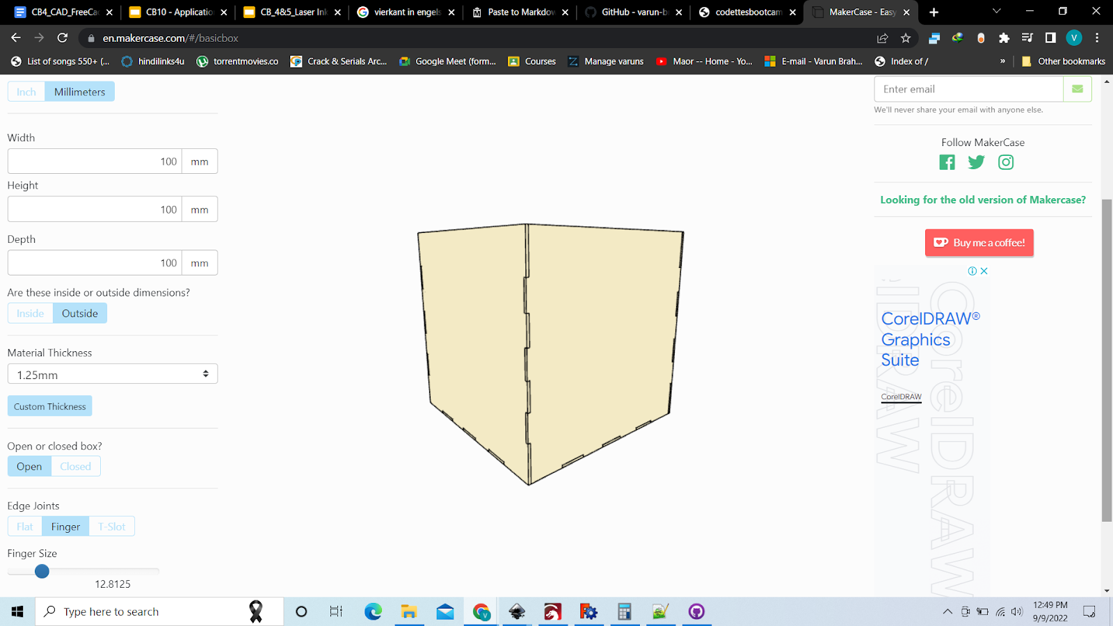
Select milimeters, and the parameters and the rest of the things, those depend
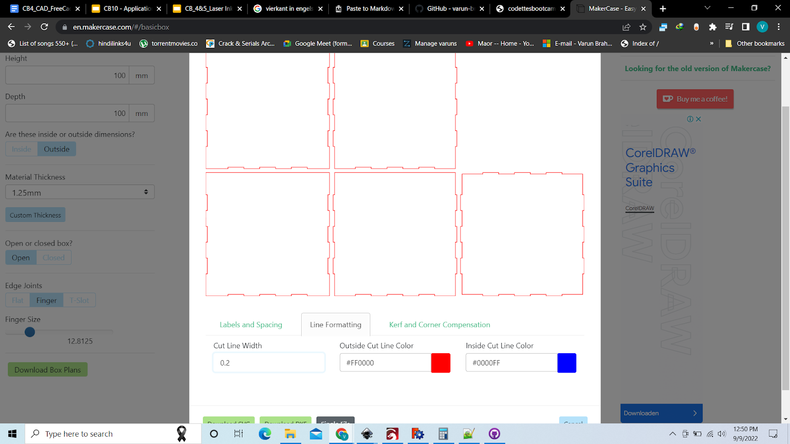

And then select Kerf and its 0.06 mm
4.7 Inkscape

First we launch inkscap and open a New document.
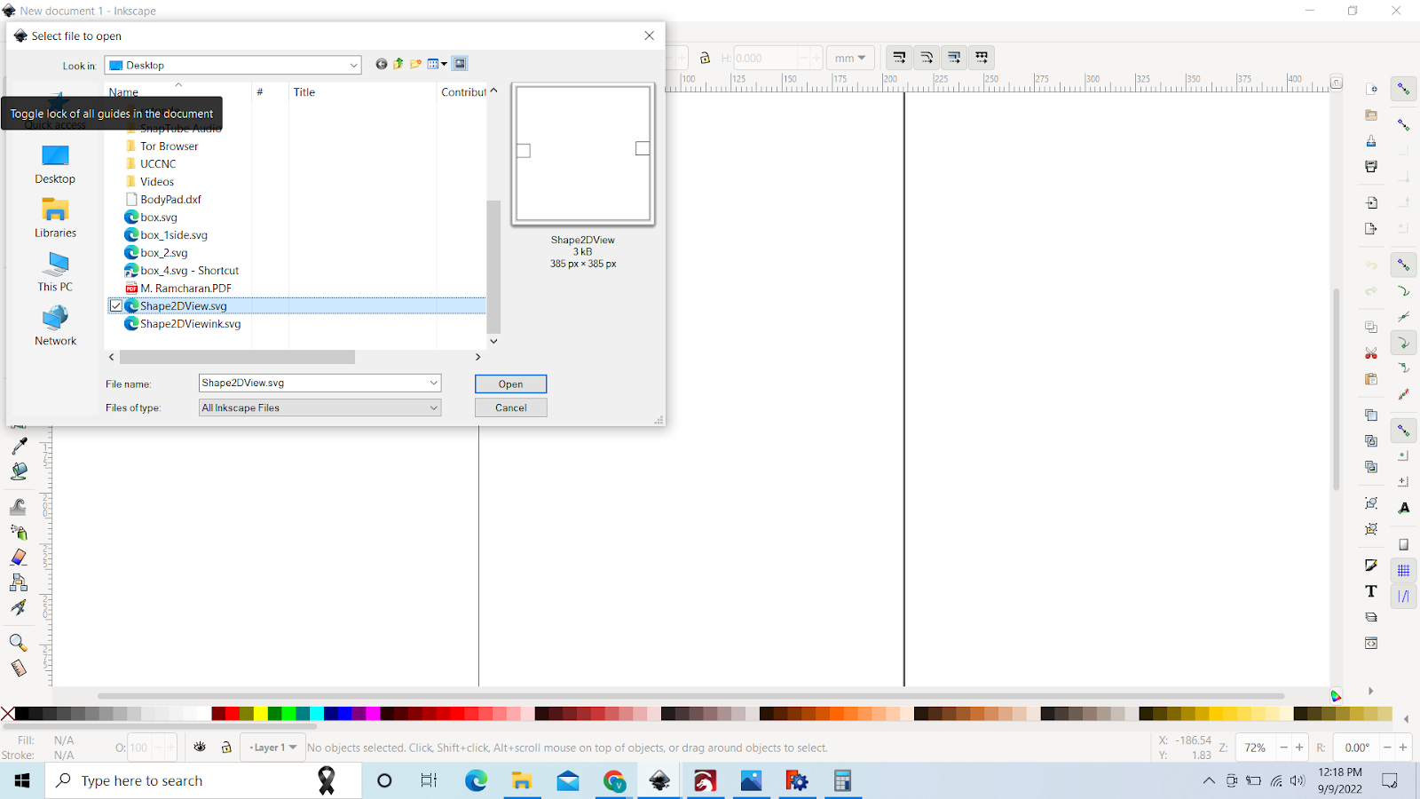
Then we need to import our SVG, we go to FIle->import-> and select the SVG
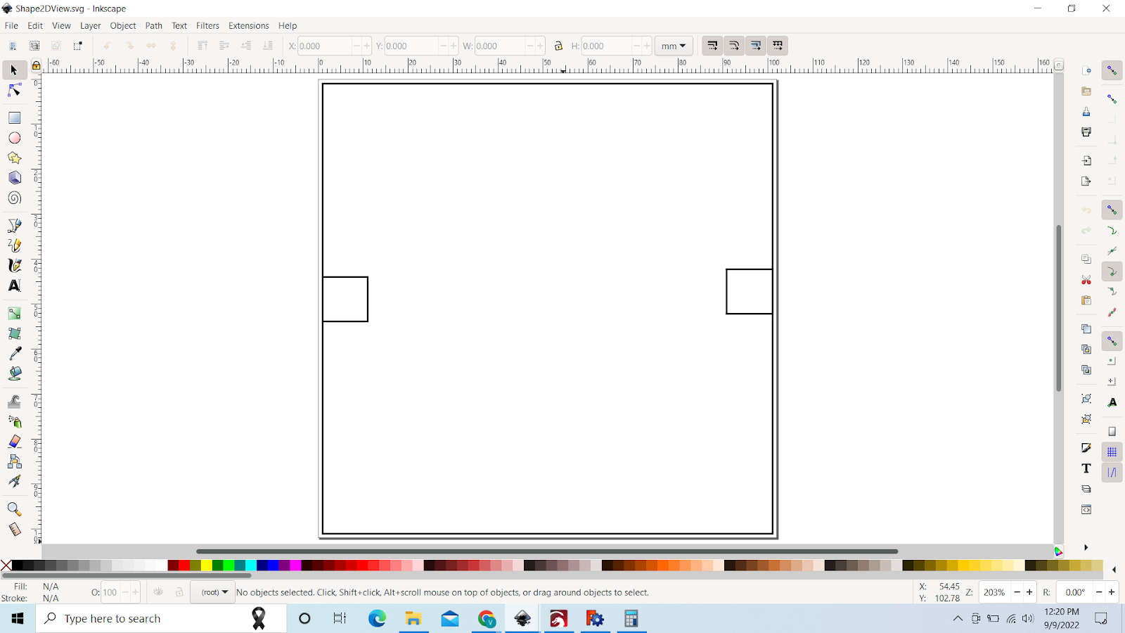
Then our SVG is imported
Then we click on the kinda pen icon and open fill and stroke

We select our object and if we want to cut it, we make i bright RED(255,0,0)
If we want a picture engraved on it, we can do the following

We can go to File->Import-> and just select the picture

Then we have our picture, but this isnt ready for caming yet, so we go to Path-> Trace Bitmap

Then we will get something like this, ust click on update
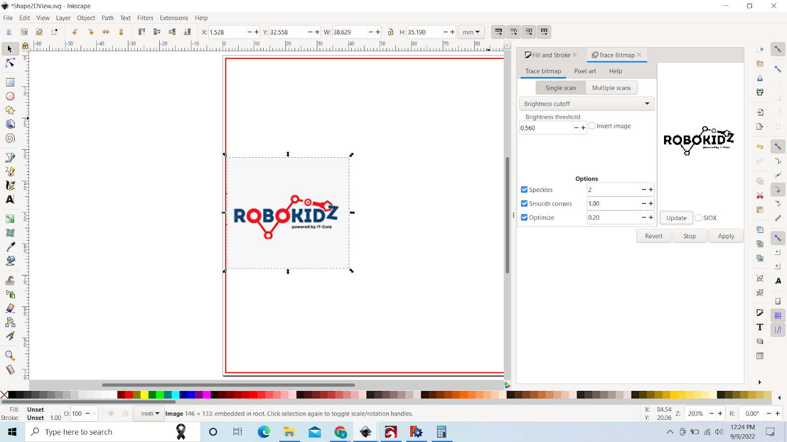
and if the picture isnt clear just up the Threshold and when good, just click on Apply

Now both pictures are in one, we can just delete the old one and adjust the new one

Like this
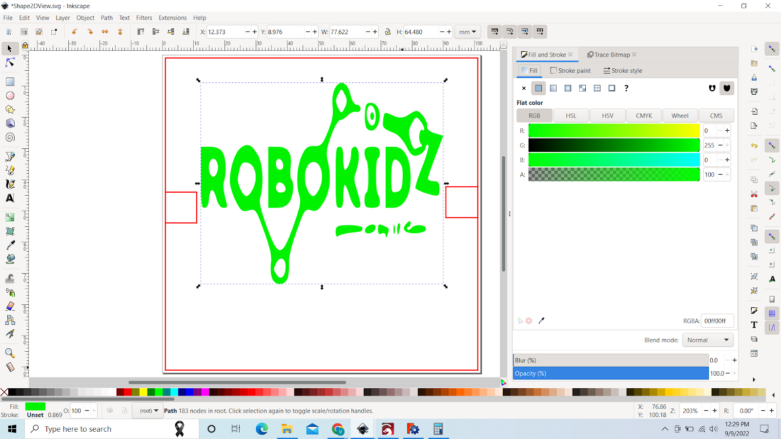
Then we can Go to FIll and stroke again, but to fill this time and fill it with another color

Then we can save the file, just go to File-> Save as-> and just put ink after the name
Chapter 5: CNCC ================
5.1: Stepcraft
We had to design something related to our final project to cnc, so i designed the magnet holder for my submarine
Just 4 pockets in a circle
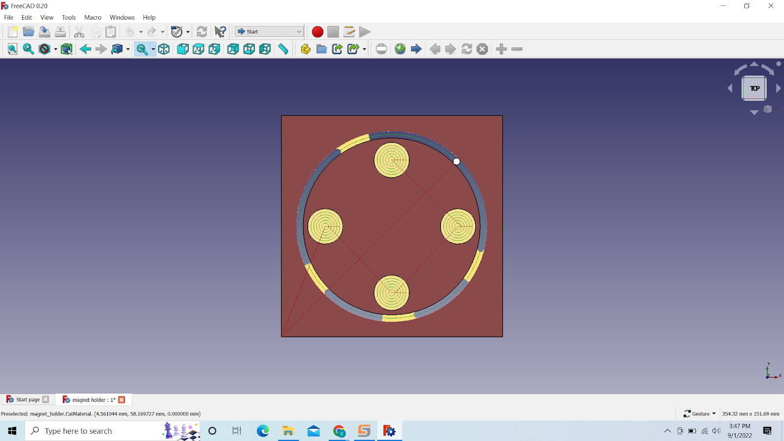
The diameter of the magnet is 16mm, and the whole diameter is 80 mm.
After that we open the uccnc stepcraft_840

We first press on reset to connect to the stepcraft. And load the uccnc file.

We need to change the feet speed to F1000.000
I can’t demonstrate after this with pictures, But i will try to explain
we need to secure our stock to the stepcraft and then
We now have to move the drill bit over our design to check if it will fit
and need to set our null points, of the Z the null point is on the stock itself.
Then we need to put the drill bit on
and the vacuum to make sure it doesn’t get dusty.
Notes:
-
If something goes wrong, press the red button on the side of the cnc
-
Vacuum on the stock as well, to make sure nothing hinders the drill bit
-
The drill needs to be turned on and off manually
-
Always cnc with your laptop on power
5.2 Laser
Now we are gonna work with the Laser.
Under here we have the parameters for the laser
CUTTING
| \ |
Power
70
Speed
10
ENGRAVING
| \ |
Power
20
Speed
70
MATERIAL
| \ |
Slot width
Material-2* kerf
Kerf
0.06
Line width
0.2
Kerf: (the Thickness of the laser beam when its gonna cut,so have to adjust our design to make sure we get the perfect cut)
Power: The power of the laser
Speed: The speed which the laser moves with
For that we need a 2D design, We can use Freecad or makerspace.
-
Fill the laser with water on the backside, make sure there is no air in it
-
And we also adjust the height of the laser
-
Turn on the laser controller, NOT THE LASER
-
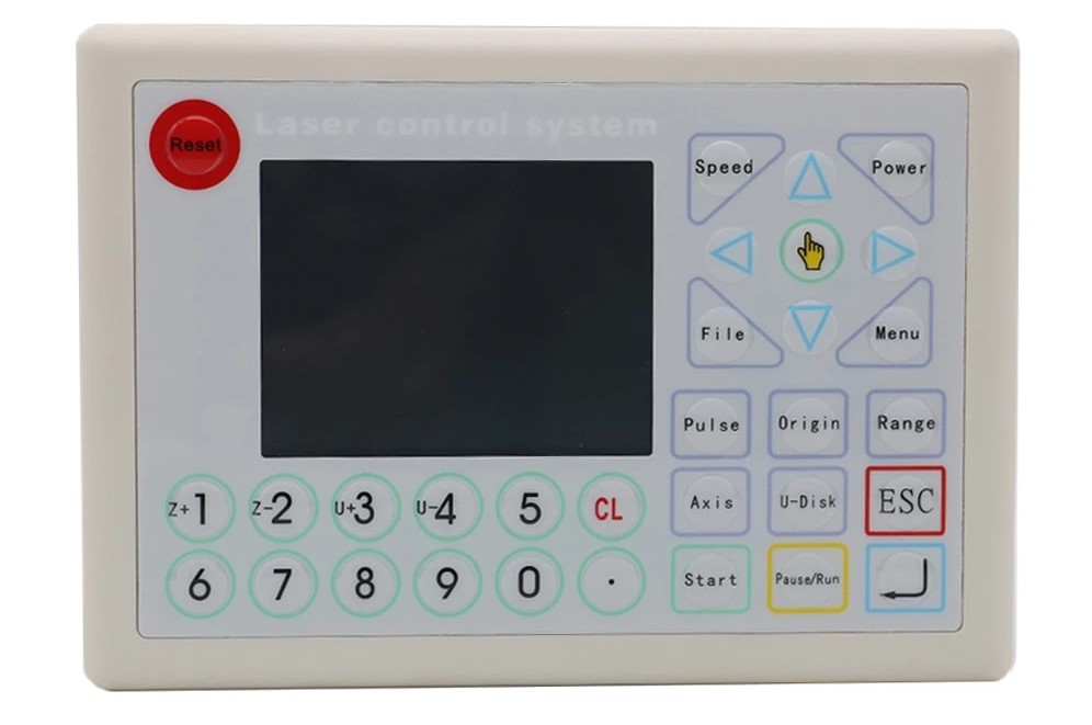
This is the laser controller, on this we can see all the details that we need,
-
If this is the first time of that day, We pulse the laser to make sure everything is fine
-
First we adjust the laser to the point on the stock that we want to use, and then we pulse it, if the line is too wide, that means the laser is to high or low, so we have to adjust the height again
-
Then we can send our design to the laser with the usb cable, if u hear a beep and see ur design on the screen ,means ur good to go, if not just try again, or different usb ports
-
And go to the place you want the laser to start cutting at and click on Origin
-
Then we click on Range to check if everything is fine , not too big or small, not going out of stock etc.
-
IF everything is fine, we click on Start
So this is it for the laser, basics, lets get into using it
First we need a design, Check chapter 4.6 and 4.7 For that
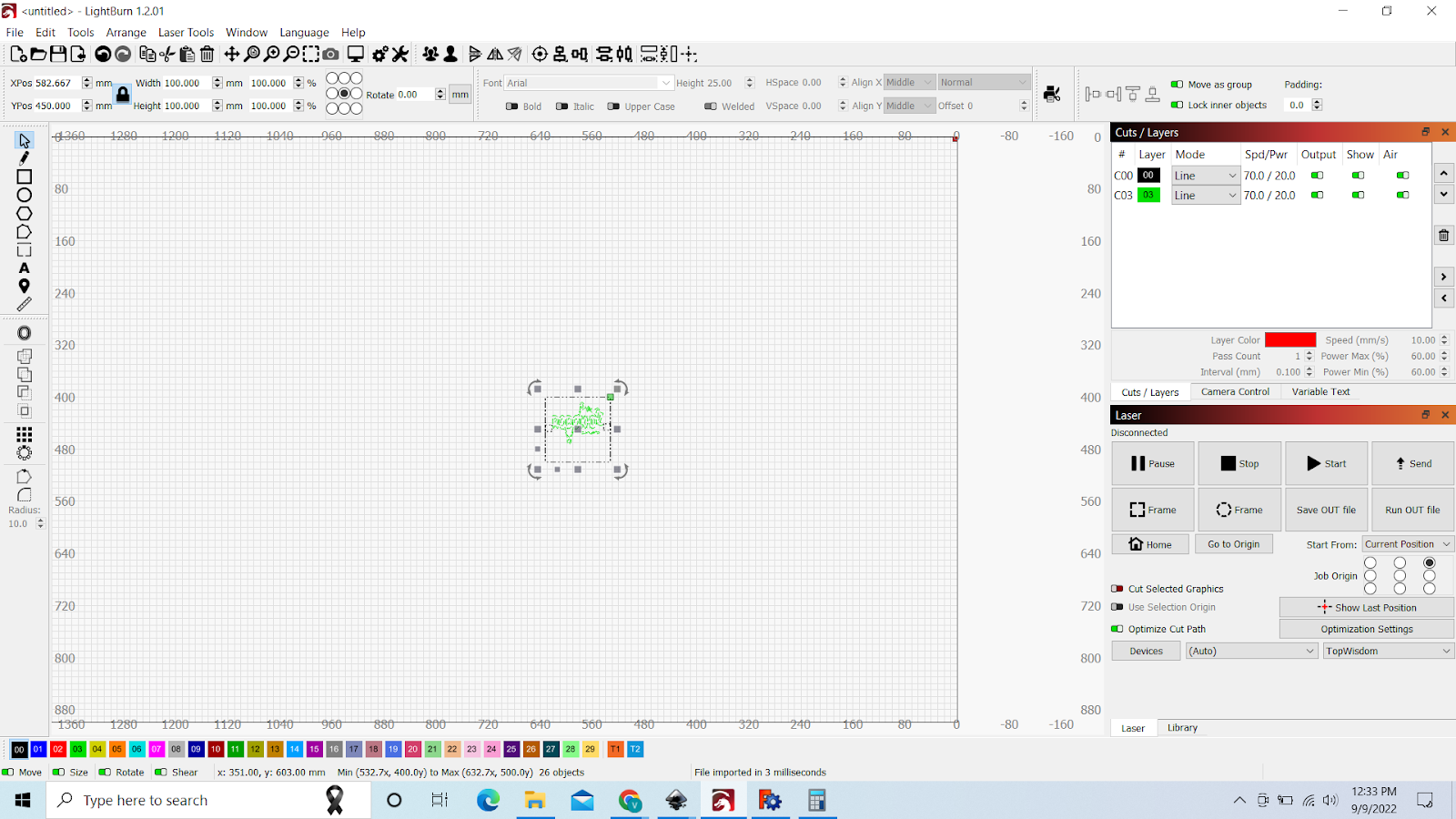
Then we open lightburn and import the files, File->import->select the SVG

Put the whole design in the top right corner and as u can see, there is no red color, i made a mistake in the inkscape then, but no worries, BLACK is cutting and GREEN is engraving then, First make sure the cutting color is always on the bottom,

LIke this
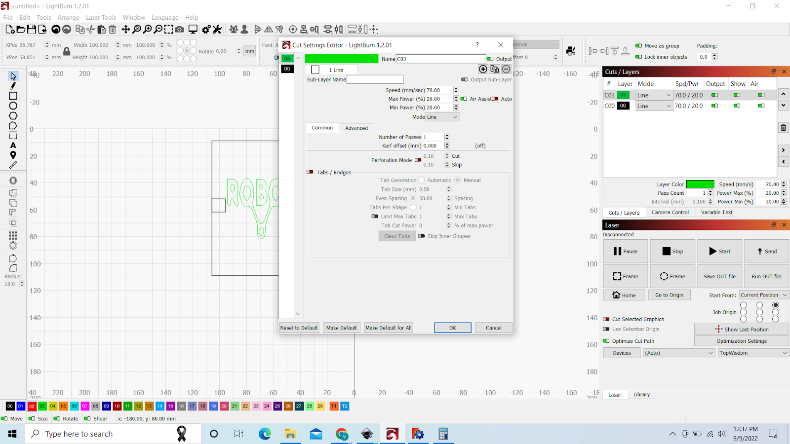
For engraving these parameters are correct, Power 20% and speed 70
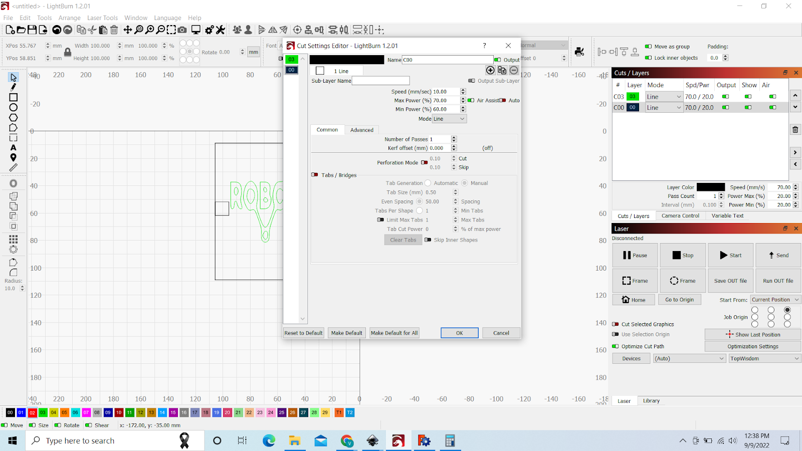
For cutting the parameters need to be, Power 70% speed 10

If all is correct, just click on send
This is the laser controller, on this we can see all the details that we need,
-
If this is the first time of that day, We pulse the laser to make sure everything is fine
-
First we adjust the laser to the point on the stock that we want to use, and then we pulse it, if the line is too wide, that means the laser is to high or low, so we have to adjust the height again
-
Then we can send our design to the laser with the usb cable, if u hear a beep and see ur design on the screen ,means ur good to go, if not just try again, or different usb ports
-
And go to the place you want the laser to start cutting at and click on Origin
-
Then we click on Range to check if everything is fine , not too big or small, not going out of stock etc.
-
IF everything is fine, we click on Start
Chapter 6: Electronic design =============================
So now we have to make our own arduino or yeah bord using a microcontroller unit(mcu)
For that we use kicad, So how do we begin
First we of course have to download kicad and some libraries. Then we need to install kicad
6.1 installation and setup
And just click through
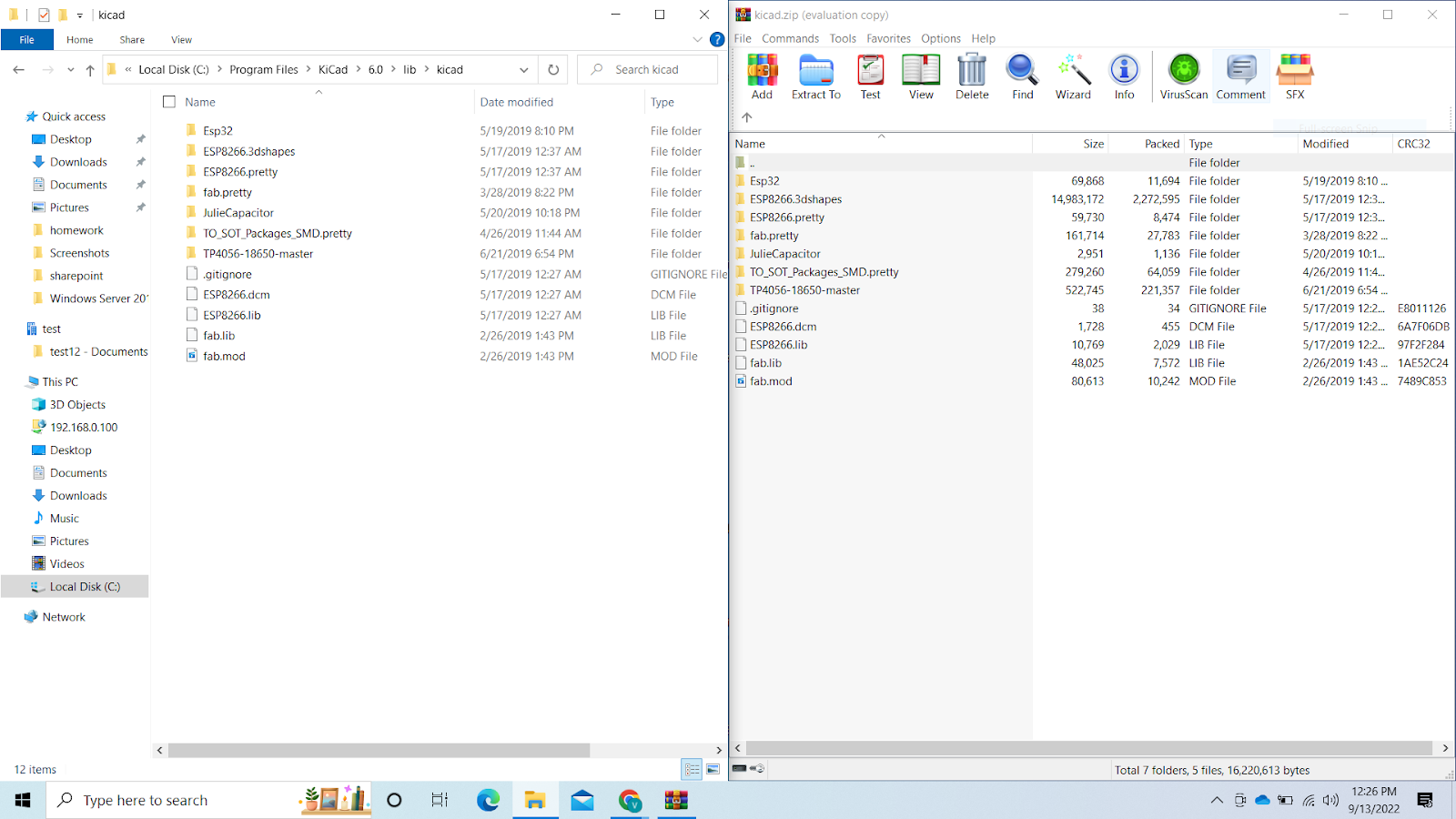
Then we can take those libraries from the zip and import it in
C:\Program Files\KiCad\6.0\lib\kicad
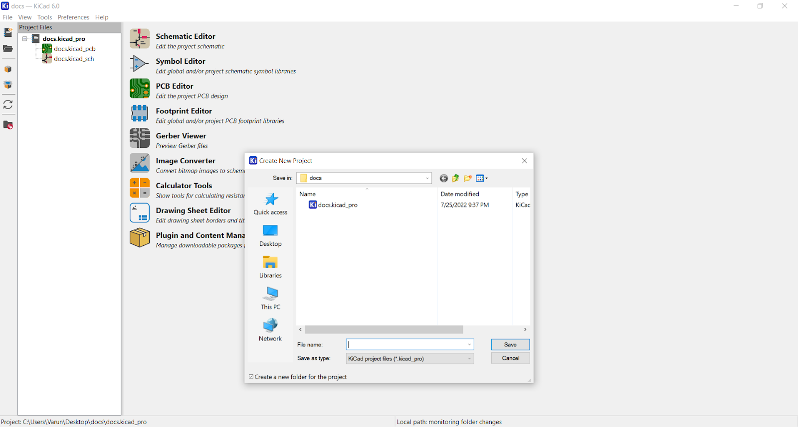
After that we can open kicad click on new project and create one
And we select schematic view
And we should get something like this
First we need to import our libraries before we can continue
We go to Preferences-> Manage symbol libraries
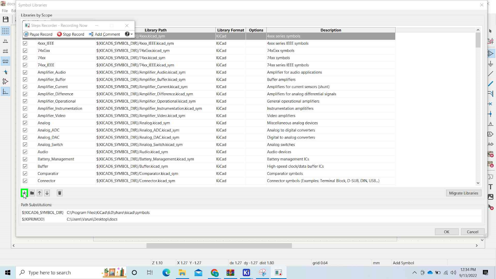
We add a new row

Then select browse

Go to C:\Program Files\KiCad\6.0\lib\kicad and select fab.lib
Okay now we also need to import the libraries to annotate
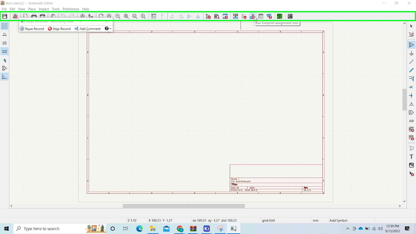
We click on Run footprint assignment tool

We click on Preferences-> Manage libraries and click on new and browse
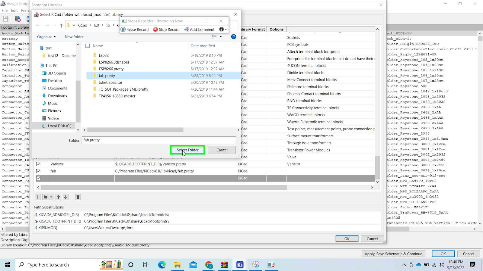
This time just select the folder fab_pretty and click on select folder
That is it for the installation and setup of the environment
Now to the real work
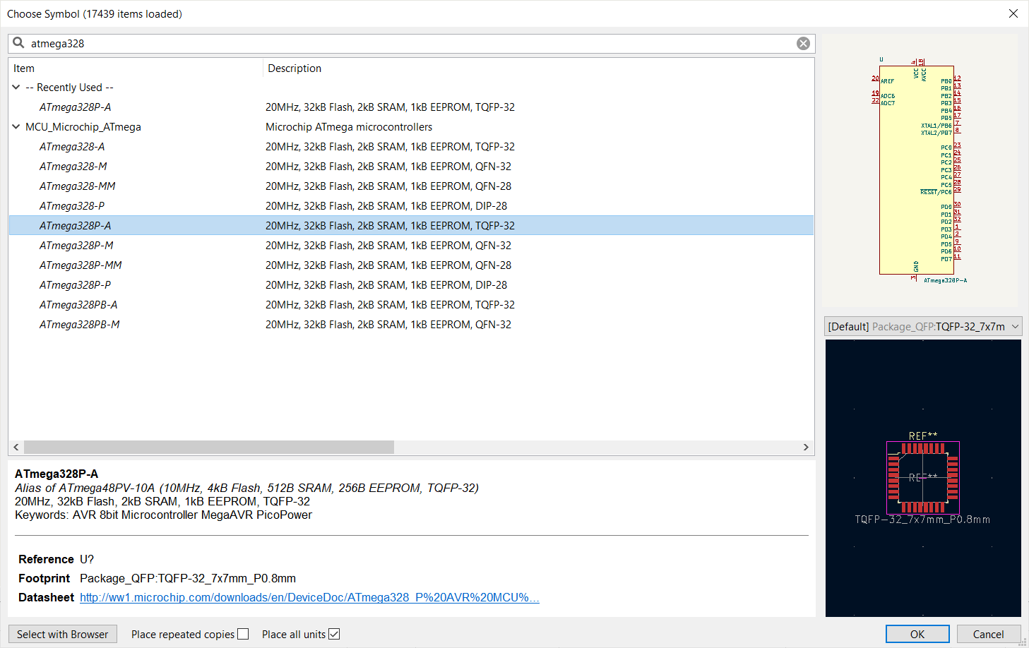
6.2 Schematic
First we have to import everything
Components that we are gonna use are
-
1*Atmega328p-a
-
2*capacitors (CAP-US1206)
-
2*Resistors(RES-US1206)
-
1*Led
-
1*Resonator
-
1*Avrisp
-
1*FTDI-SM-HEADER
-
1*6MM-Switch
-
2*6 pin female connectors
-
2*8 pin female connectors
Atmega328P-A
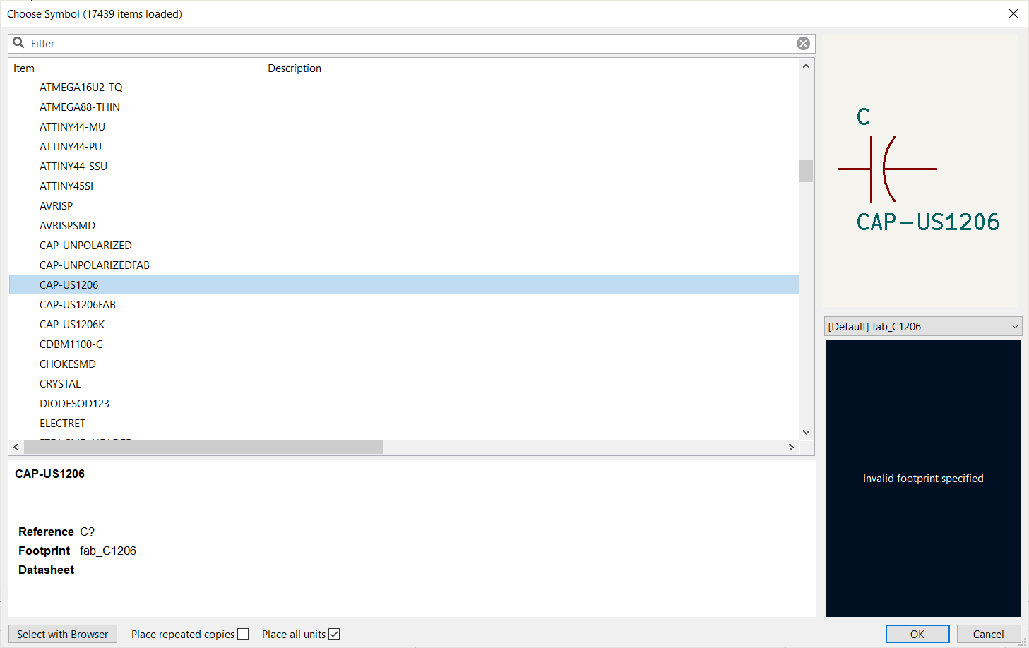
CAP-US1206

Resistors(RES_US1206)

LED

RESONATOR

AVRISP

FTDI-SMD-HEADER

6MM_SWITCH6MM_SWITCH

Conn_01x06_Female

Conn_01x08_Female
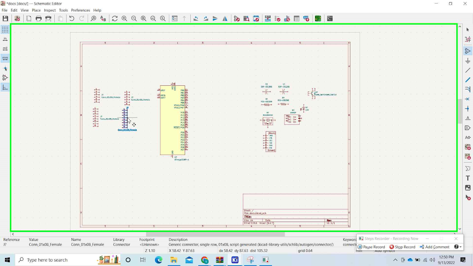
Once you have everything on the schematic board its time to connect them
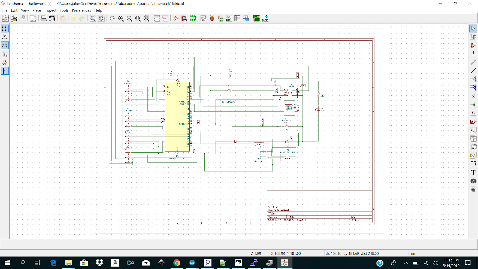
And we could use this picture as reference, i wont go on how to connect each wire, but start small, i started on the left side and connect one by one, you cant rush this or you will make mistakes
But okay, once everything is connected or wired up, we need to assign footprints

Click on Run footprint assignment tool and then annotate and once here, you can go to fab on the left and the list will pop up on the right, from there select the prints as in here and then click on apply,save & continue. If everything is right, nothing will happen or pop up

Then go to file-> Export-> Netlist and click on export netlist

6.3 PCB board editor
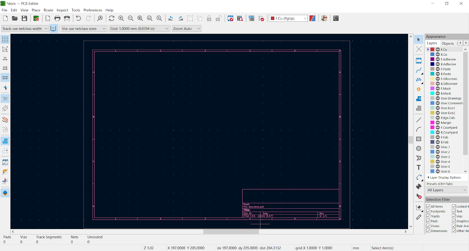
Welcome to the PBC BOARD EDITOR, also knows as HELLLLLLLL!!!!!!!!!!!!!!!!!!

GO to File-> Import-> Netlist, Then select the file, click on load en test and then update PCB
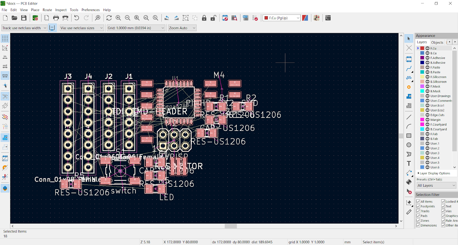
THEN you will be stuck with this mess
I cant guide you how to fix this, its a puzzle, you just need to puzzle it out, but here are a few tips
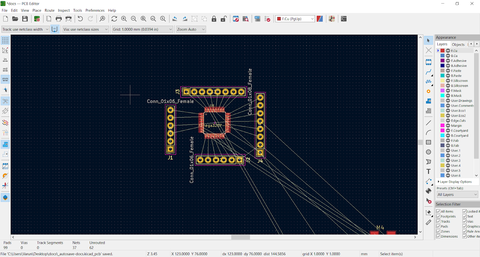
First move everything out of the way and keep the io’s and position them around the board, rotate them etc. Now you have this, much simpler
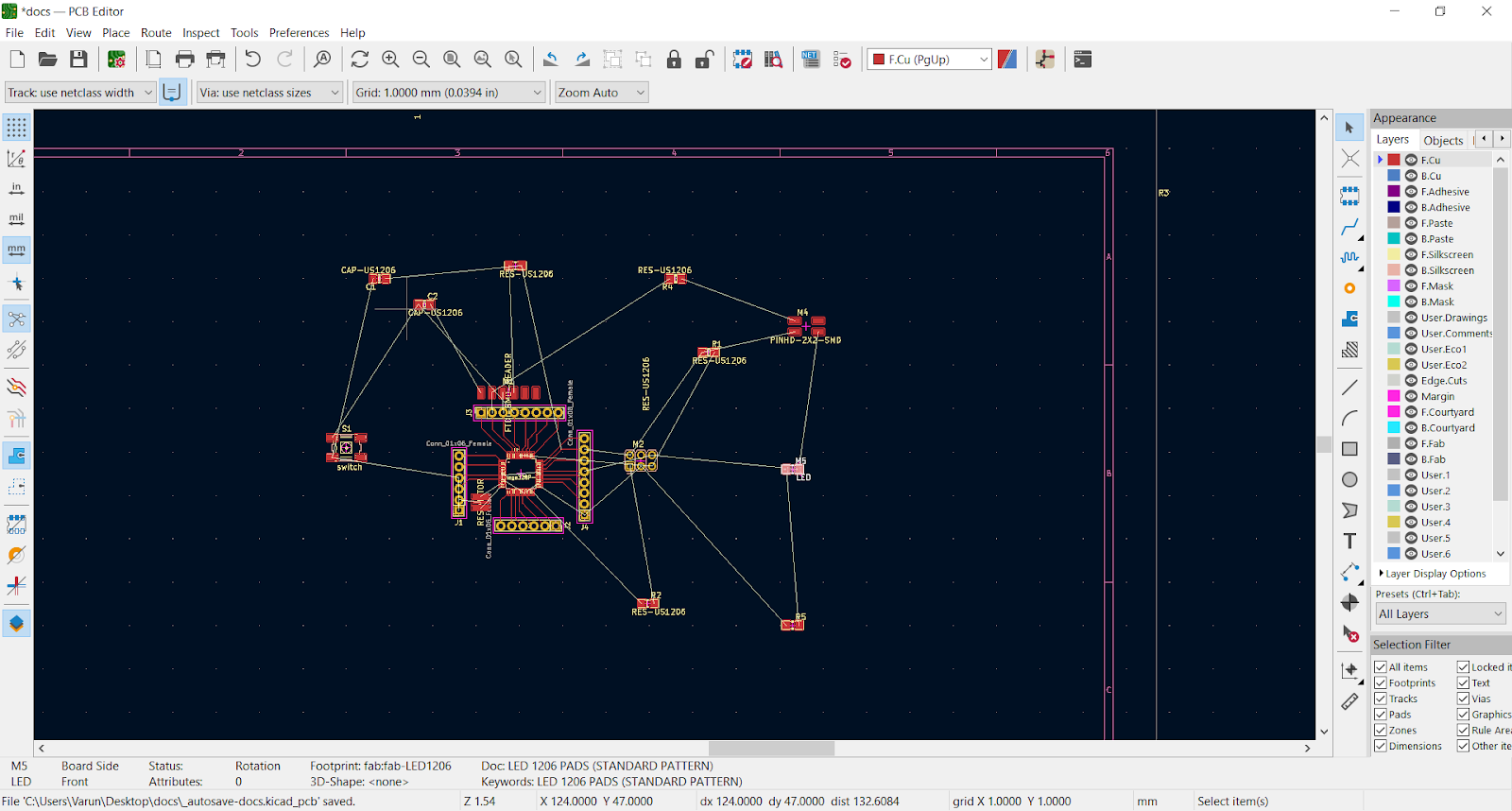
And now connect the io’s and bring back the other stuff and spread them apart, now its just a game of connecting and playing around
In the end i had this
And now we have to continue with it
Chapter 12: Final Project =============================
Final documentation
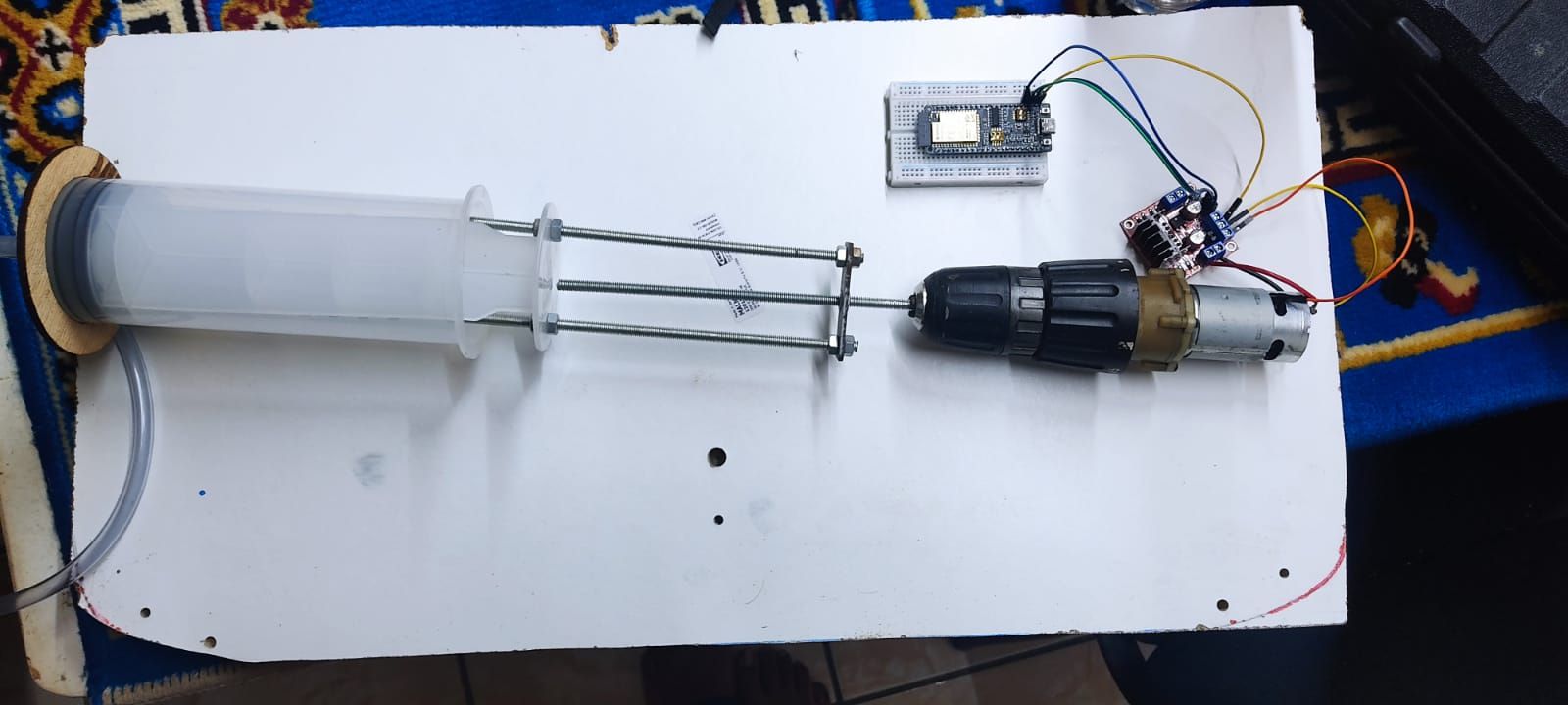
So for my final project, I am building a submarine, So how did i get started and what did to get here as of today its 20-1-2023 10 0 clock at night, So i jumped blindly into this and i had no idea how submarines even work, so i started research on that and found out they work with ballast tanks, So air is lighter then water,so when there is water in the tank the submarine is heavier and sinks but when there is air in the tank the submarine is lighter, So now my problem, since i am not gonna build a really big submarine, i have around 1kg to play around with or 10N, Almost nothing. Second thing is Communication, i know that wifi signals dont work underwater, so what now, RADIO,
Physical Build
But first things first, i can put communication on a hold for a sec, but the ballast tanks are more important, So lets get building i would say
Ballast tanks
-
research
-
Shopping
-
Logic/ building
1.Research
So how do the ballast tanks work, Well from the videos i watched,Most of them fake i found real one it looks like they used a syringe, and something to move it somehow
So the problem with this is, that is it a moving part inside a closed space, not that much of an issue, but it has to like extend to the back, so that part kept me busy for a long time.
Works:
But i took a bolt and put it against a wall and saw that if i rotate it around its axis, the bolt it self stays in the same place, but the nut on the bolt, moves itself, so there i had my answer, i had to make the moving part of the syringe the nut and the rest of it the bolt to say so.
2. So first i bought a like rod on which a nut could like walk and a bunch on nuts and i ordered the syringe from amazon

3. So after that i started building with the help of my dad, we did it in like an hour, so we didn’t really have any pics of the building, but we have a video of the end result
https://drive.google.com/file/d/12Kf_LXws27O5j4G9DfCABOmAb7oNQHuw/view?usp=share_link
Final troubleshooting:
But 2 things that i saw after the build was done is that, i need a fast and high torque motor. Not two of the best combination, but we were using a drill to test the syringe, so i had a broken drill lying around, so i took it apart and used that motor for the pump
So i tried controlling my motor with the l298n, but something was burning, so i turned it off, for the final that i have now, is my ballast tank that i can control with a drill, not the most iot way, but something and here is my final prototype
Holder
So to hold the syringe in the pipe i also have created a design in freecad and lasered it once,
First i had to measure the diameter of the syringe which is 70mm and the diameter of the pipe is 102mm, So i created my design in freecad
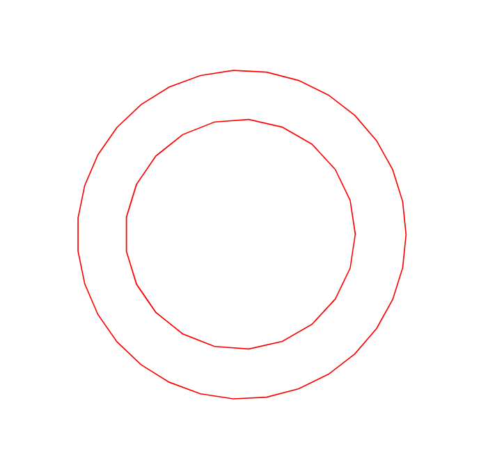
So it looks something like this.
So thats for the ballas tanks, Now the movement
I still haven’t figured that out and i am kinda lost on that part, So i am still brainstorming on that
Fi
Code
So thats that for the physical build, now software based
So my whole submarine will be controlled by a webapp, now lets see how far i got
So i first build the basic movements in the app,
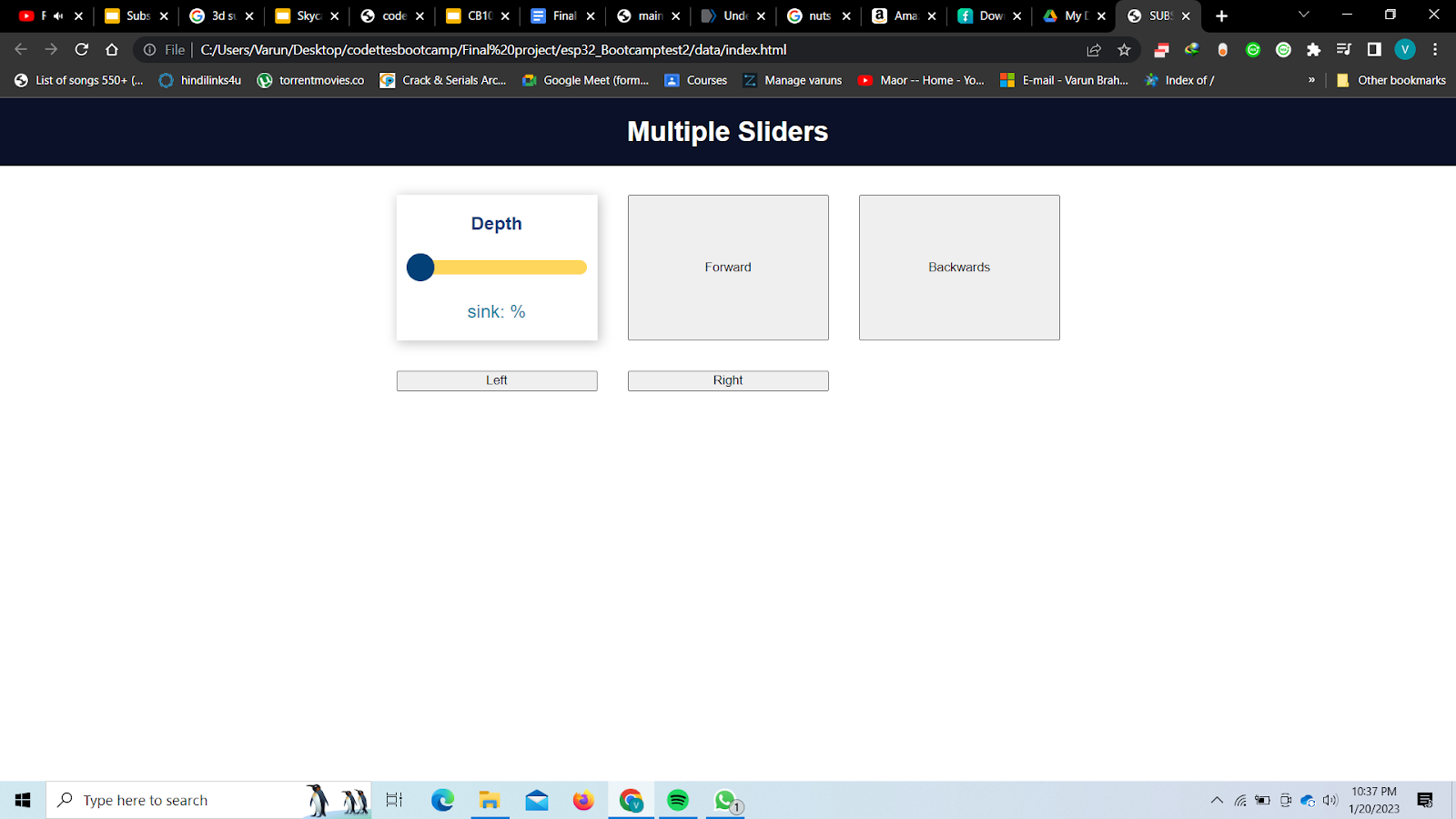
As you can see i have a basic front,back,left, right and its a sub, so also up and down
And it can call a function on my esp32
https://drive.google.com/file/d/1l-SWLY19tTEE1o8wEdGQpien8GGYyn8w/view?usp=sharing
But i notices that it is giving me trouble, so i think imma need to use an arduino, but i wanted to try the esp32 one more time, so i am gonna test that tomorrow and give the results, and i also updated my dashboard a bit, caused it looked boring

A bit better i would say, simple enough to understand tho.
So thats the code part.
So here under i put the research links, every website i visited and got something off in here,
Pictures, videos, documentation, research of other people
Ballast tanks
https://create.arduino.cc/projecthub/aruna5/autonomous-underwater-vehicle-a7a53a
https://qph.cf2.quoracdn.net/main-qimg-29f56dbb281c9c958277c216812a2197
https://www.youtube.com/watch?v=pUba126uzvU
https://www.youtube.com/watch?v=kEanKJhZvA0
https://www.youtube.com/watch?v=O0NUXnxgax8
Check list: Build ballast tanks
Communicatie
https://www.ncbi.nlm.nih.gov/pmc/articles/PMC3355409/
https://www.youtube.com/watch?v=NcLn61cqdak
https://www.youtube.com/watch?v=cq5fDZrWNWA
https://www.youtube.com/watch?v=zhkN9V1SI-A
And here under i did some calculations, didn’t work out tho, but still
Submarine calculations:
Fz=m.g
1*10
= 10N
Fw= pgv
= 1.10.1m3
Oppervlakte cylinder= πr.r.h
1= 3.14.r.r.0.5
h=50cm
r=0.8m= 80cm
h=1m
r=56cm
h=0.5
r=10
Fb = Vs × D × g
3.14.5.5.50=0.003925m3
fw= 0.0157110= 0.517N
Components:
-
servo 3* 60g each
-
Dc motors 1* 100 g
-
Magnets 200g
-
Arduino mega 37g
-
Additional : 200g
Total weight: 180+100+200+37+200= 717g
Fz=m.g
0.717.10= 7.17 N
F